
Electric Power Generation System Using Hydro Turbine Tracted by Paraglider

a hydro turbine and paraglider technology, applied in the direction of electric generator control, machines/engines, mechanical equipment, etc., can solve the problems of insufficient strength, high cost of high-rise tower construction, and insufficient surface wind, so as to reduce maintenance requirements, free of serious safety problems, and light weight

Inactive Publication Date: 2010-01-07
KIM JONGCHUL
View PDF1 Cites 11 Cited by
  • Summary
  • Abstract
  • Description
  • Claims
  • Application Information

AI Technical Summary

Benefits of technology

[0015]The tethered paraglider, which is the structure adopted in this invention to extract the energy from the high quality wind existing at high altitude, is light in the aspect of the mass per unit area and the forces exerted on the structure are mainly tensile, therefore it is light-weight and free of serious safety problem. Also it reduces the requirement of maintenance because of little moving parts.
[0016]And the diameter of the hydro turbine blade decreases less than 1 / 20 of the diameter of the windmill rotor blade when we use directly winds, by using the water of which density is 800 times of the air, to derive the hydro turbine for extracting the energy originally from winds; it reduce the cost of turbine manufacturing.
[0017]In addition, the operation rate of wind power generation is high, because it can get off the typhoon area and move to the better area for wind power as the seasonal upper-air condition. In case that the wind power is not available, it is possible to generate with tidal stream in anchorage at the place of strong tidal stream.

Problems solved by technology

Using windmills on the ground is an obvious and general way to generate electricity from the wind, however, it has many problems conflicting each other as an aspect of promoting efficiency.
The windmills which use even moderate wind are not appropriate for sudden and strong gust.
Because the winds near the ground (the surface wind) are capricious and not strong enough in comparison with the wind at high altitude.
It is very expensive to build a high tower to use the wind at high altitude.
At the higher altitude, we can get more abundant and cleaner wind power but the rotor staying in high altitude is not safe and not easy for maintenance.

Method used


Image

  • Electric Power Generation System Using Hydro Turbine Tracted by Paraglider
  • Electric Power Generation System Using Hydro Turbine Tracted by Paraglider
  • Electric Power Generation System Using Hydro Turbine Tracted by Paraglider

Examples


Embodiment Construction

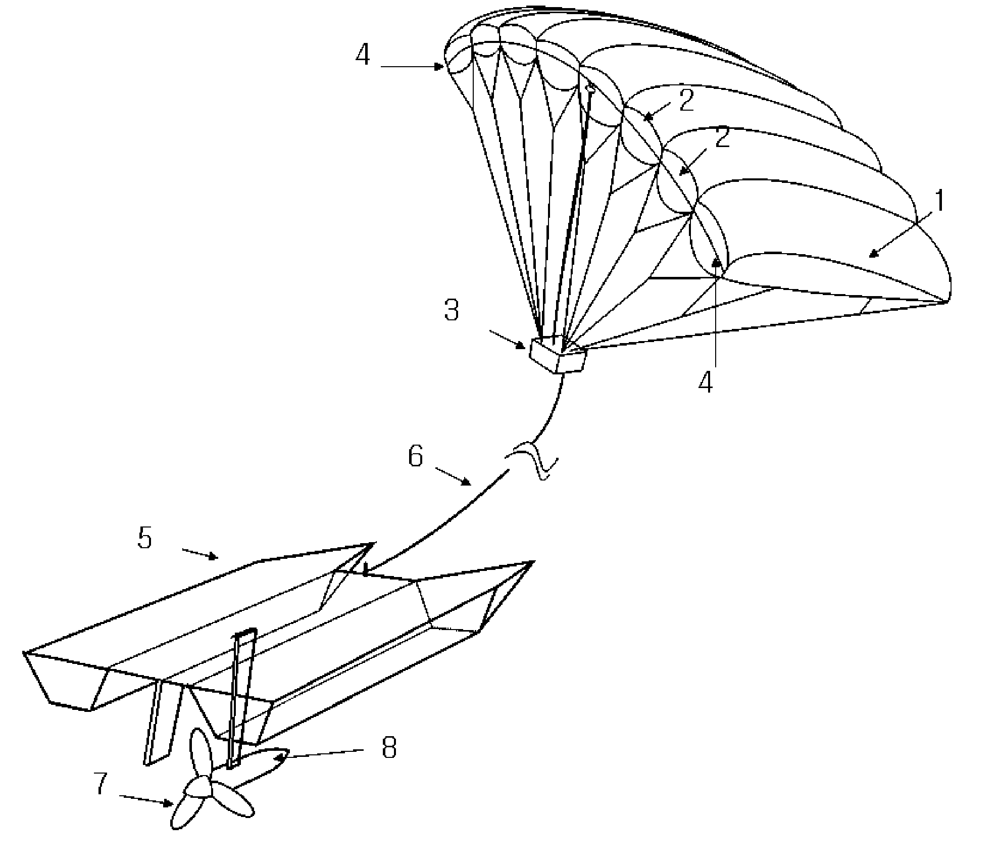
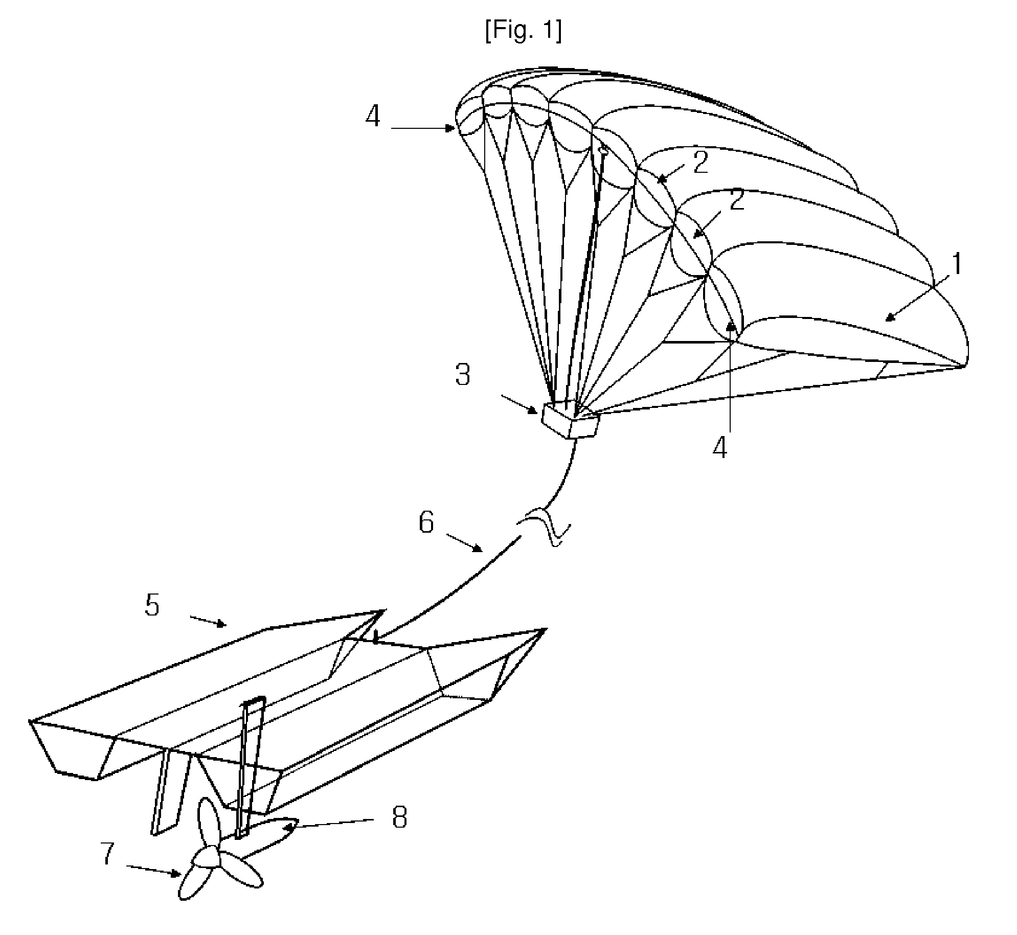
[0029]The tethered paraglider controlled by FBY (Fly-By-Wire) would fly up at least 500 M above sea level to gather the plenty wind power in this invention. Even though the mechanical moving parts are minimized, the electricity is required in the upper air for de-icing, lightings for aircraft collision avoidance and for driving FBW servo motor. The electricity can be recharged to a battery at the time of periodic maintenance or through the electric wire from the floating platform. But we can reduce frequency of landings by using regular rotary windmills or solar batteries mounted on the parafoil.

[0030]It is better to install the hydro turbine generator under the floating platform for the stability against wave, but it is inconvenient for maintenance. It's desirable to lift up the hydro turbine and generator on the floating platform in case of maintenance.

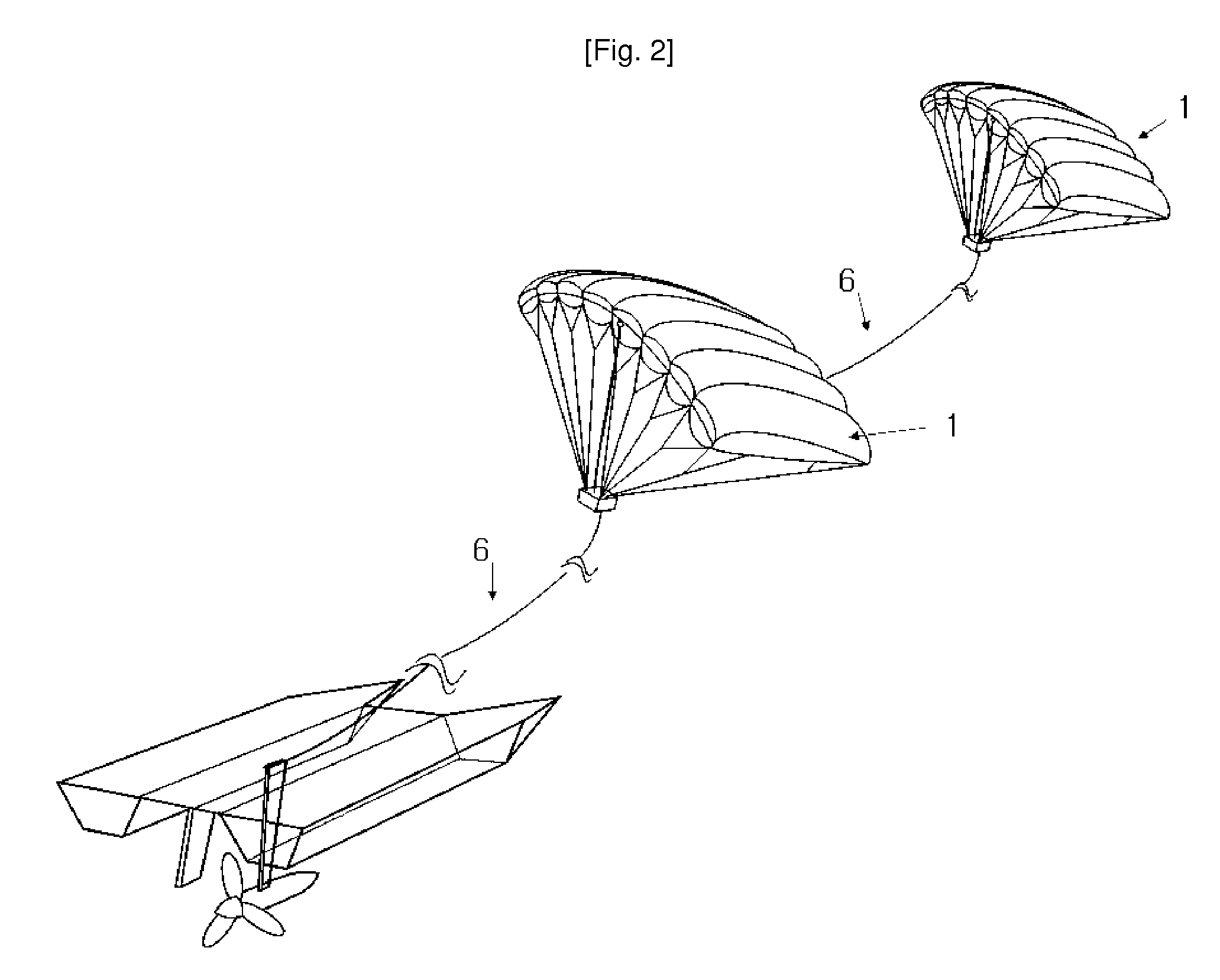
[0031]It is desirable to gather the wind power at the altitude of 10 Km above by using the cascaded tethered paraglider technique,...


PUM


Abstract

As an electric power generation system using the high altitude wind which is more steady and stronger at the high altitude up to about 15Km above sea level, the power generation system consists of a rotary generator (8) derived by a hydro turbine (7) attached under a ship-like floating platform (5) towed by a parafoil (1) flying at high altitude, controlled by a servomotor (3), which is remotely controlled through electric wire or wireless communication. Accordingly, the diameter of the turbine driven by sea water is reduced as 1 / 20 in comparison with the windmill which uses directly high altitude wind, and the periodical maintenance becomes convenient by locating the heavy mechanical moving parts near the surface of sea.

Description

TECHNICAL FIELD[0001]This invention relates to the generation of electricity using the wind power; and more particularly, to the generation of electricity with a hydro turbine towed by a paraglider flying at high altitude.BACKGROUND ART[0002]Using windmills on the ground is an obvious and general way to generate electricity from the wind, however, it has many problems conflicting each other as an aspect of promoting efficiency. The windmills which use even moderate wind are not appropriate for sudden and strong gust. Because the winds near the ground (the surface wind) are capricious and not strong enough in comparison with the wind at high altitude.[0003]It is very expensive to build a high tower to use the wind at high altitude. To avoid building a high tower, the methods of using a self floating power generator in the air such as windmill attached to an airship or rotors of a gyrocopter are sometimes adopted. (U.S. Pat. No. 4,470,563, U.S. Pat. No. 6,781,254 B2 and etc.)[0004]At ...

Claims


Application Information

Patent Timeline
IPC IPC(8): F03D9/00F03B13/00
CPCF03B17/061F03D9/008F05B2240/921Y02E10/725F05B2240/93F05B2240/931Y02E10/28F05B2240/922Y02E10/30Y02E10/72Y02E10/20
Inventor KIM, JONGCHUL
Owner KIM JONGCHUL
Learn More