Display device, a receiving device and a method for driving the display device

Inactive Publication Date: 2010-01-07
SHARP KK
View PDF8 Cites 27 Cited by
  • Summary
  • Abstract
  • Description
  • Claims
  • Application Information

AI Technical Summary

Benefits of technology

[0019]In addition, it is preferable that the light source block in its blinking operation is arranged so that a turn-on time period of the light source block is shorter as the moving image moves faster. Further, it is preferable that the light source block during the turn-on time period in its blinking operation is arranged so that a light amount of the light source block increases as the turn-on time period in its blinking operation is shorter.
[0020]According to the display device having the above-described configuration according to the preferred embodiment of the present invention and the method for driving the display device, the light source including the plurality of light source blocks divided and arranged in a matrix is evenly placed behind the display panel, one frame of the video input signal is divided into the plurality of frame blocks each corresponding to the size of each of the light source blocks, the light source block corresponding to the frame block the image of which has been judged as a moving image is arranged to blink upon receipt of the optical responses from the display cells, and the light source block corresponding to the frame block the image of which has been judged as a still image are arranged to be kept turned on, whereby the backlights are arranged to blink only for a portion of the moving image on the screen. That is to say, since the backlights are arranged to blink only a portion of the screen, not for the whole screen, blurring of the moving image is prevented and flicker is reduced compared with a full flash-type backlight turn-on system or a full sequential scanning-type backlight turn-on system which are used in the prior arts.
[0021]In this case, when the light source block driving unit is arranged to turn off the light

Problems solved by technology

However, it is pointed out that the liquid crystal display device has a disadvantage that when an image including a moving image portion is displayed, an edge of the moving image portion is seen blurred, which is so-called “blurring of a moving image” in contrast to a cathode ray tube (CRT) display device which is conventionally used mainly for such a purpose.
Accordingly, in th

Method used


Image

  • Display device, a receiving device and a method for driving the display device
  • Display device, a receiving device and a method for driving the display device
  • Display device, a receiving device and a method for driving the display device

Examples


Embodiment Construction

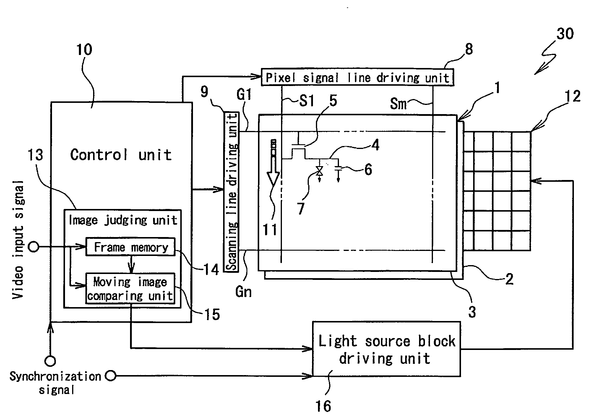
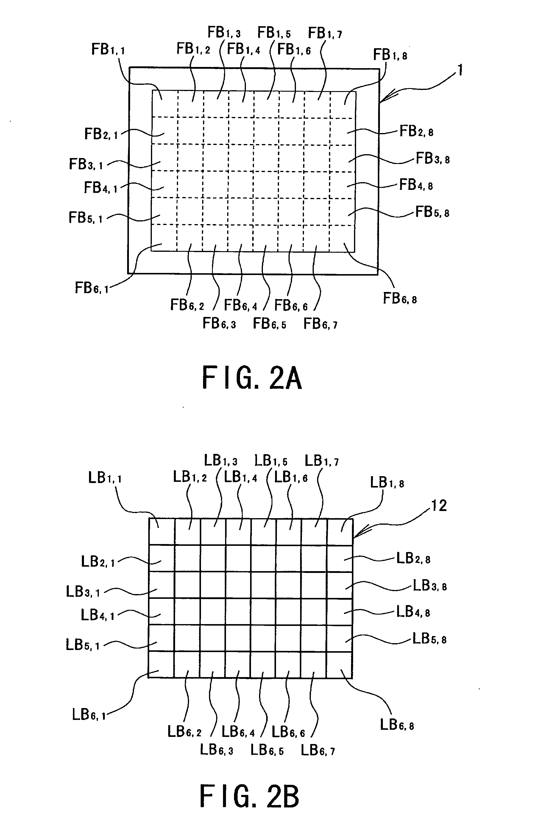
[0034]A detailed description of a display device according to a preferred embodiment of the present invention will now be provided with reference to the accompanying drawings. FIG. 1 is a view showing a schematic configuration of the display device, FIG. 2A is a view schematically showing one frame of an video input signal which is divided into a plurality of frame blocks, FIG. 2B is a view schematically showing a light source defining backlights which is divided into a plurality of light source blocks in the display device, and FIGS. 3A to 3C are views schematically showing specific examples of the light source in the display device.

[0035]A display device 30 includes a liquid crystal display panel 1 and a light source 12 including a plurality of light source blocks.

[0036]The liquid crystal display panel 1 includes an allay substrate 2 and a common substrate 3 made of a glass substrate which are placed to be opposed to each other at a given interval via liquid crystal, and the commo...


PUM


Abstract

One embodiment of the device includes a display panel and a light source evenly placed behind the panel, wherein the light source includes light source blocks divided and arranged in a matrix, includes an image judging unit which divides one frame of a video input signal into frame blocks each corresponding to a size of each of the light source blocks and judging whether images of the frame blocks are moving or still, and a light source block driving unit which blinks the light source block corresponding to the frame block the image of which is judged as moving by the judging unit upon receiving optical responses from the cells while turning on all the time the light source block corresponding to the frame block the image of which is judged as still by the judging unit.

Description

BACKGROUND OF THE INVENTION[0001]1. Field of the Invention[0002]The present invention relates to a display device which is excellent in image display quality.[0003]2. Description of the Related Art[0004]In recent years, a liquid crystal display device is widely used as a display unit of a home electric appliance such as a computer and a television. However, it is pointed out that the liquid crystal display device has a disadvantage that when an image including a moving image portion is displayed, an edge of the moving image portion is seen blurred, which is so-called “blurring of a moving image” in contrast to a cathode ray tube (CRT) display device which is conventionally used mainly for such a purpose. In the conventional CRT display device which performs display by scanning an electron beam and makes a fluorescent material emit light, an impulse-type display method is adopted in which emission of light from pixels is generally pulsed though persistence of the fluorescent material...

Claims


Application Information

Patent Timeline
IPC IPC(8): G09G3/36G09G5/10G09G5/02
CPCG02F1/133603G02F1/133604G02F2001/133397G02F2001/133601G09G3/3426G09G2320/106G09G2310/0237G09G2310/08G09G2320/0247G09G2320/0261G09G2320/064G09G3/3648G02F1/133397G02F1/133601
Inventor TAKATA, YOSHIKI
Owner SHARP KK
Why Eureka
Try Eureka