
Package substrate structure

a substrate structure and packaging technology, applied in the direction of electrical apparatus construction details, printed circuit non-printed electric components association, semiconductor/solid-state device details, etc., can solve the problems of high cost, high cost, and high cost of the above-mentioned semiconductor package, and achieve good thermal conductivity of the metal board, reduce the overall package height, and desirable heat dissipation performance

Active Publication Date: 2010-01-07
UNIMICRON TECH CORP
View PDF8 Cites 12 Cited by
  • Summary
  • Abstract
  • Description
  • Claims
  • Application Information

AI Technical Summary

Benefits of technology

The present invention provides a package substrate structure that can reduce the package height and has good heat dissipating performance. The structure includes a substrate with a cavity, a metal board mounted on the substrate, and solder masks with openings corresponding to the wire-bonding pads and ball-implanting pads. The substrate can also have conductive pads, a semiconductor chip, bonding wires, and an encapsulant. The structure can further include a surface treatment layer on the wire-bonding pads and a dielectric layer between the substrate and the solder mask. The semiconductor chip can be attached to the metal board or the dielectric layer. The package substrate structure reduces the overall package height and provides desirable heat dissipating performance.

Problems solved by technology

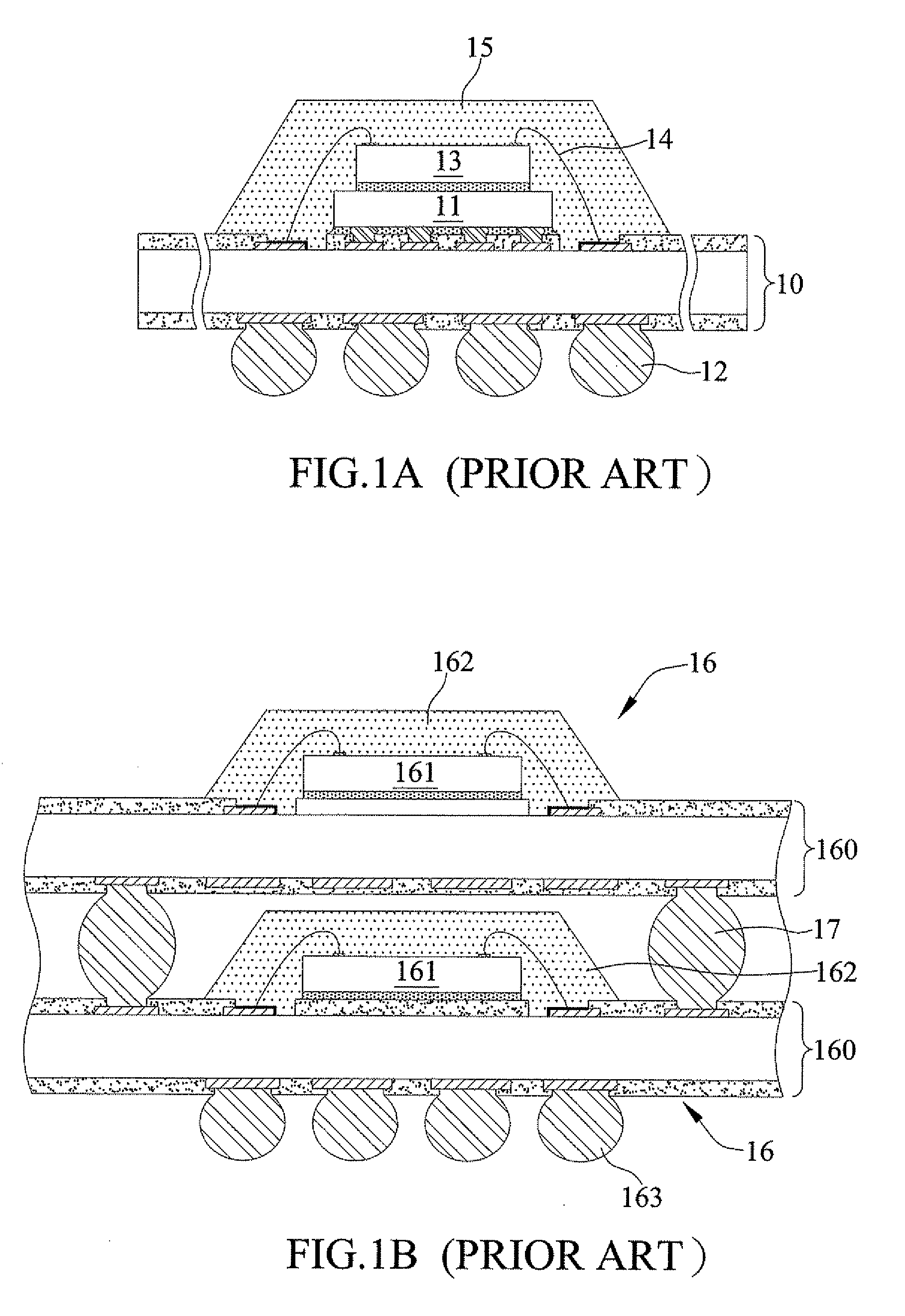
However, a cost issue has been raised for the above chip-stacking semiconductor package because the first and second semiconductor chips 11, 13 are electrically connected to the same said substrate 10.
In such case, if one of the semiconductor chips is defective, the semiconductor package as a whole would fail.
And, it only allows the yield test to be conducted on both the semiconductor chips as a whole instead of each single semiconductor chip, such that once a defect is found, the semiconductor package as a whole must be discarded.
This is not cost-effective.
However, the POP semiconductor package has a limit in size.
In such case, the overall height of the semiconductor package would easily exceed the expected range, and the POP semiconductor package thus fabricated is hardly compact, leading to its limited applicability in electronic devices.
Another issue is overheating.
With the semiconductor chip 161 being encapsulated by the encapsulant 162, heat generated by the semiconductor chip 161 in operation is accumulated rather than efficiently dissipated, and in consequence the semiconductor chip 161 is likely to be overheated and damaged.

Method used


Image

  • Package substrate structure
  • Package substrate structure
  • Package substrate structure

Examples


Embodiment Construction

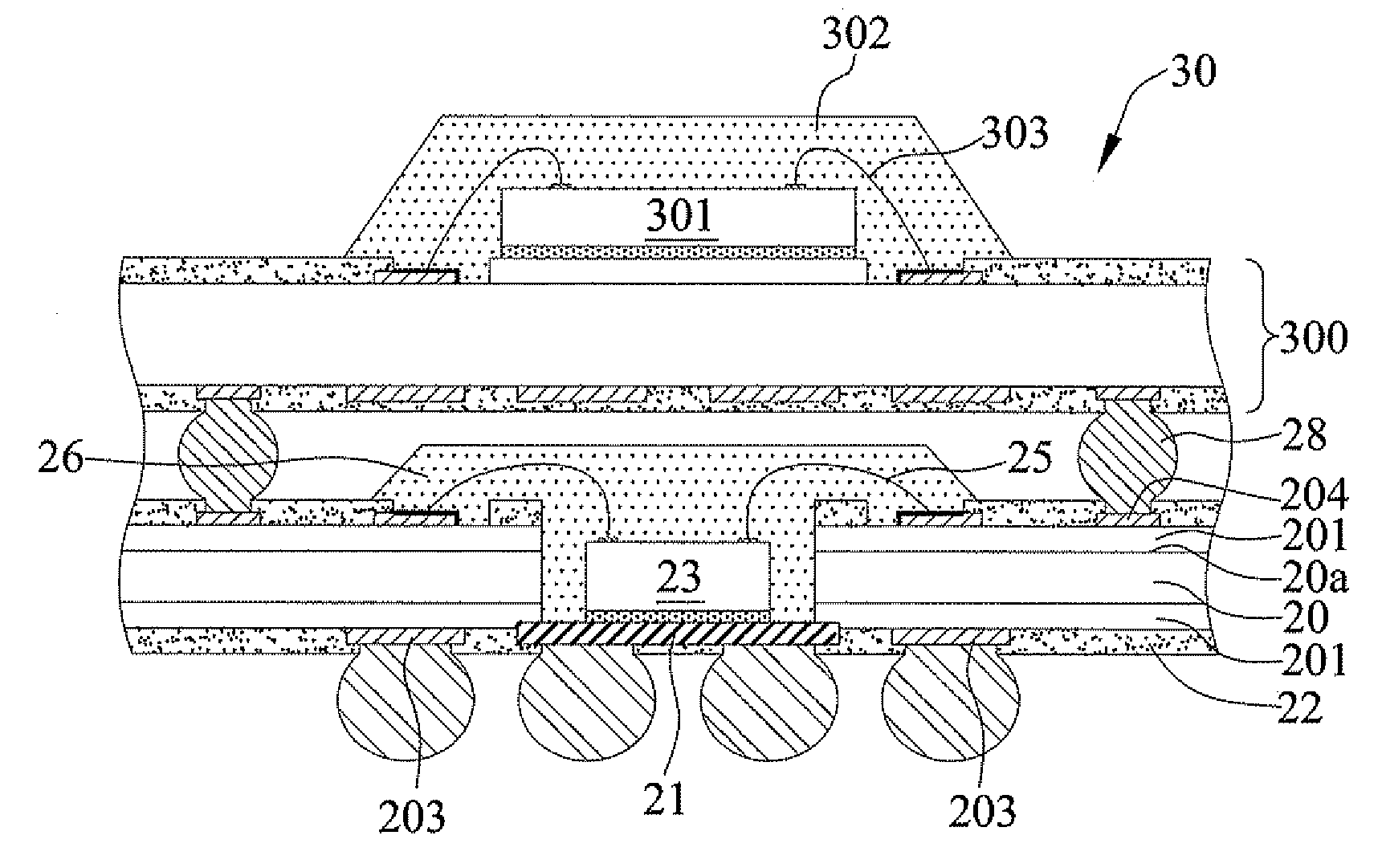
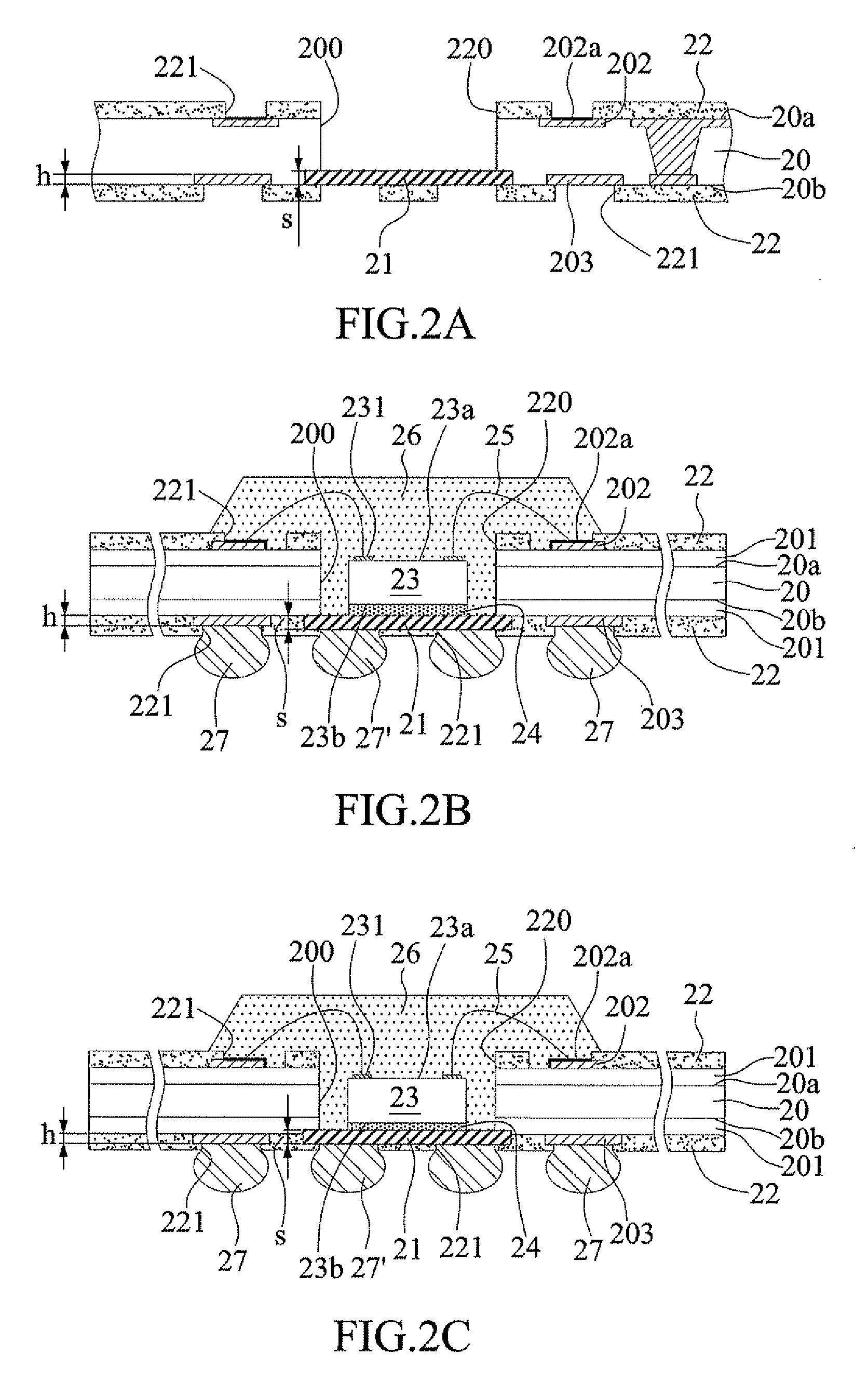
[0020]Preferred embodiments of a package substrate structure, its combination with a semiconductor chip and a package stacking application as proposed in the present invention are described below by reference to FIGS. 2A through 2E and FIG. 3. It should be understood that the drawings are schematic diagrams only showing relevant components in the present invention, and the practical component layout could be more complicated.

[0021]FIG. 2A is a cross-sectional schematic diagram of a package substrate structure in accordance with the present invention. As shown in FIG. 2A, the package substrate structure comprises a substrate 20, a metal board 21 and solder masks 22.

[0022]The substrate 20 is a two-layered or multi-layered package substrate completed with a predetermined circuit layout, wherein the circuit layers within the substrate or on surfaces of the substrate are electrically connected to each other by conductive vias or plated through holes. A plurality of wire-bonding pads 202 ...


PUM


Abstract

A package substrate structure includes: a substrate having a first surface and an opposing second surface and characterized by a plurality of wire-bonding pads provided on the first surface of the substrate, a plurality of ball-implanting pads provided on the second surface of the substrate, and at least a cavity formed to penetrate the first and second surfaces of the substrate; a metal board mounted on the second surface of the substrate and covering the cavity, wherein the metal board has a thickness greater than that of the ball-implanting pads and has an area greater than that of the cavity; and solder masks disposed on the first and second surfaces of the substrate respectively and having at least a solder-mask cavity corresponding in position to the cavity of the substrate, the solder masks further having a plurality of openings for exposing the wire-bonding pads, the ball-implanting pads and the metal board.

Description

FIELD OF THE INVENTION[0001]The present invention generally relates to package substrate structures, and more particularly, to a package substrate structure with at least a semiconductor component embedded therein.BACKGROUND OF THE INVENTION[0002]Stacking of semiconductor chips is a desirable technology for its capability of meeting the requirements in high integration and miniaturization of semiconductor packages and enhancing the ability and capacity of a single semiconductor package so as for the semiconductor package to be suitable for use in low-profile, large-capacity and high-speed electronic devices.[0003]Referring to FIG. A, a conventional chip-stacking semiconductor package includes: a first semiconductor chip 11 mounted on and electrically connected to a side of a substrate 10 in a flip-chip manner; a plurality of solder balls 12 implanted to a side of the substrate 10 opposing to the side mounted with the first semiconductor chip 11 and configured to be electrically conn...

Claims


Application Information

Patent Timeline
Patent Type & Authority Applications(United States)
IPC IPC(8): H05K1/18H05K1/11
CPCH01L23/13H01L2924/15153H01L23/367H01L23/49816H01L25/105H01L2224/32225H01L2224/48227H01L2224/73265H01L2924/01046H01L2924/01079H01L2924/15311H01L23/3128H01L2224/32245H01L2224/32145H01L2224/16225H01L2225/1058H01L2225/1035H01L24/48H01L2924/00H01L2924/00012H01L24/73H01L2224/04042H01L2924/00014H01L2924/181H01L2224/45099H01L2224/45015H01L2924/207
Inventor HSU, SHIN-PING
Owner UNIMICRON TECH CORP
Learn More