Expander-integrated compressor

a compressor and expander technology, applied in the direction of positive displacement liquid engines, liquid fuel engines, piston pumps, etc., can solve the problems of affecting the performance coefficient of the system using the expander-integrated compressor, raising the temperature, etc., to suppress heat transfer, suppress oil, and high temperature during operation

Inactive Publication Date: 2010-01-07
PANASONIC CORP
View PDF38 Cites 17 Cited by
  • Summary
  • Abstract
  • Description
  • Claims
  • Application Information

AI Technical Summary

Benefits of technology

[0011]In this expander-integrated compressor, the vertical positional relationship between the compression mechanism and the expansion mechanism is not limited. However, when the compression mechanism is disposed higher than the oil level and the expansion mechanism is disposed lower than the oil level, a greater effect of preventing the heat transfer via the oil can be attained. And it has been found that an additional improvement discussed below can enhance further the effect of preventing the heat transfer.
[0018]a heat insulating structure, disposed between the oil pump and the expansion mechanism in the axial direction of the shaft, for suppressing heat transfer from an upper tank, in which the oil suction port is located, to a lower tank, in which the expansion mechanism is located, by limiting a flow of the oil between the upper tank and the lower tank.
[0019]The expander-integrated compressor of the present invention is of the so-called high pressure shell type, in which the closed casing is filled with a high temperature, high pressure working fluid. The compression mechanism, which has a high temperature during operation, is disposed at the upper part of the closed casing. The expansion mechanism, which has a low temperature during operation, is disposed at the lower part of the closed casing. The oil for lubricating the compression mechanism and the expansion mechanism is held in the bottom portion of the closed casing. The space (the oil reservoir) in which the oil is held is divided into the upper tank and the lower tank by the heat insulating structure. The heat insulating structure limits the flow of the oil between the upper tank and the lower tank, and suppresses the oil from being stirred in the lower tank.
[0020]Since the oil suction port of the oil pump is located in the upper tank, the oil pump draws primarily the high temperature oil in the upper tank. The oil drawn by the oil pump is supplied to the compression mechanism located at the upper part without passing through the expansion mechanism located at the lower part, and then returns to the upper tank. On the other hand, the low temperature oil in the lower tank is supplied to the expansion mechanism. The oil having lubricated the expansion mechanism returns directly to the lower tank. By disposing the oil pump between the compression mechanism and the expansion mechanism and using the oil pump to supply the oil to the compression mechanism in this way, it is possible to keep the expansion mechanism away from the circulation route of the oil that lubricates the compression mechanism. In other words, it is possible to prevent the expansion mechanism from being located on the circulation route of the oil that lubricates the compression mechanism. Thereby, the heat transfer from the compression mechanism to the expansion mechanism via the oil is suppressed.
[0021]Furthermore, by using the heat insulating structure in order to suppress the oil from flowing between the upper tank and the lower tank and to suppress the oil from being stirred in the lower tank, it is possible to maintain reliably the state in which the high temperature oil is held in the upper tank and the low temperature oil is held in the lower tank. In this way, the oil pump and the heat insulating structure work in combination to suppress the heat transfer from the compression mechanism to the expansion mechanism via the oil. The heat insulating structure limits the flow of the oil between the upper tank and the lower tank, but does not forbid it completely. Thus, the amount of the oil in the upper tank is not out of balance with that in the lower tank.

Problems solved by technology

Such heat transfer lowers the temperature of the working fluid discharged from the compression mechanism, and raises the temperature of the working fluid discharged from the expansion mechanism, hindering improvement of the coefficient of performance of the system using the expander-integrated compressor.

Method used


Image

  • Expander-integrated compressor
  • Expander-integrated compressor
  • Expander-integrated compressor

Examples


modified example 1

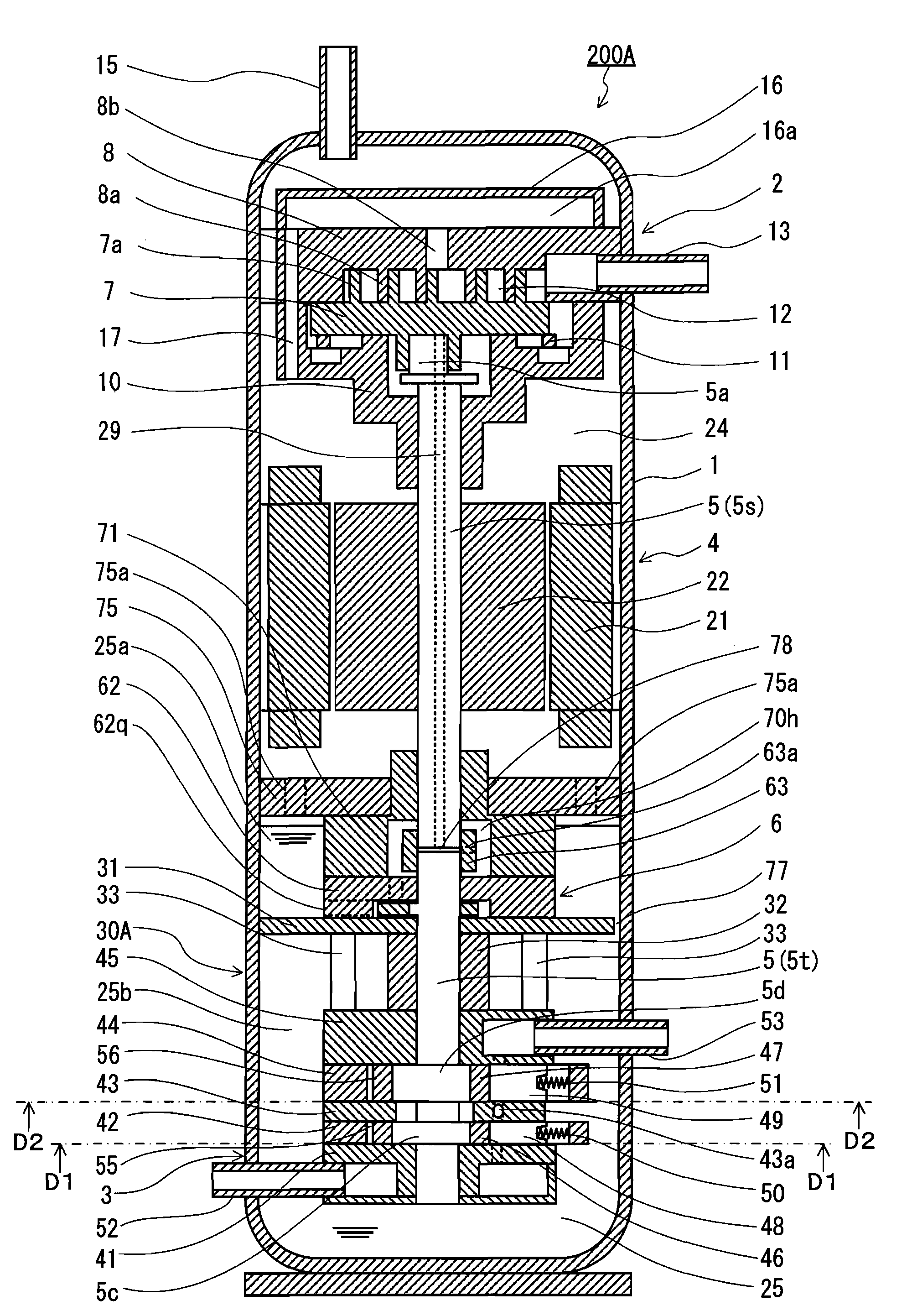
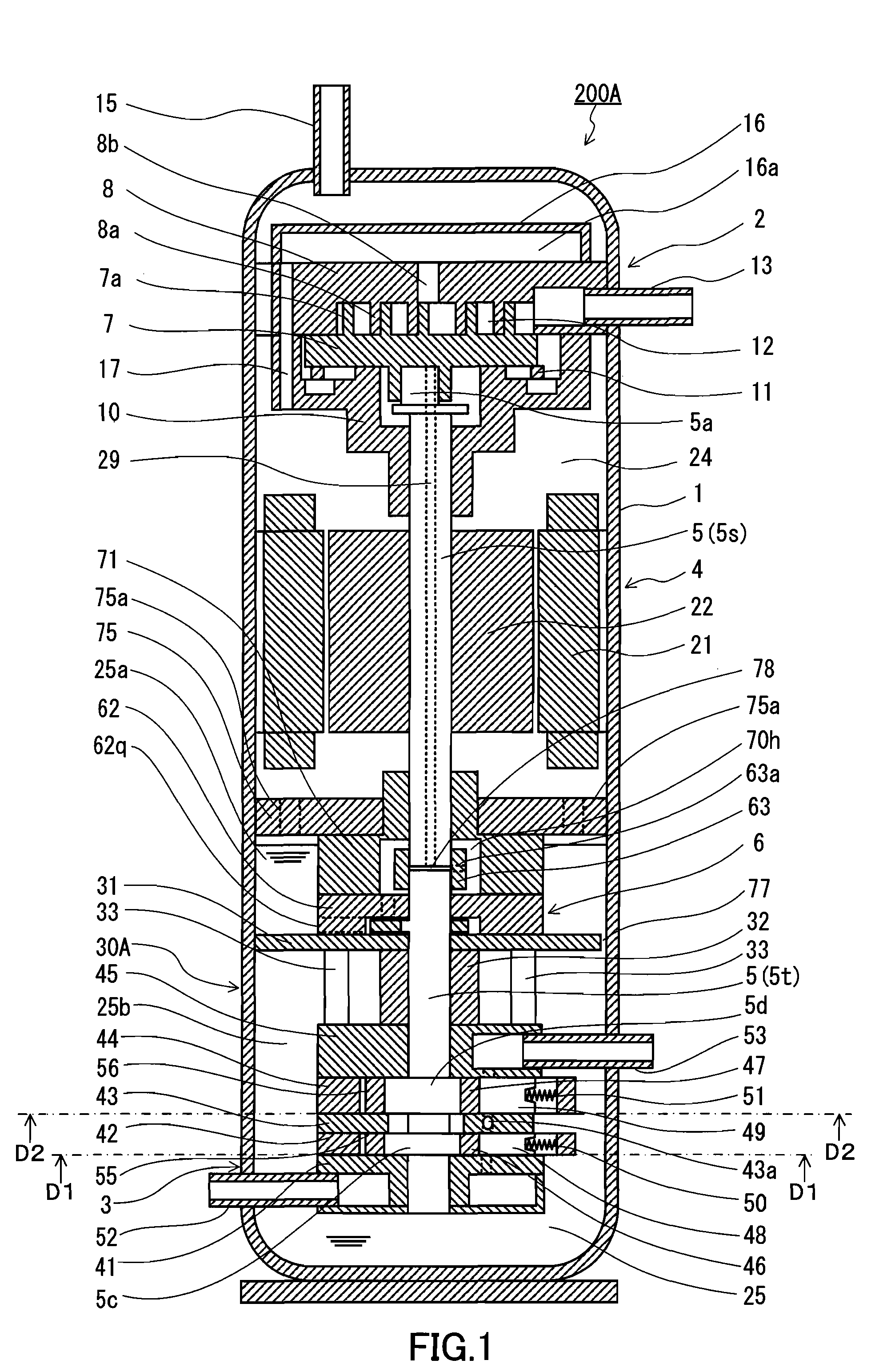
[0081]First, the locations of the oil pump 6 and the coupling portion of the shaft 5 are interchangeable vertically. In the modified example shown in FIG. 6, the oil pump 6 is disposed above the coupling portion of the shaft 5, and the relay member 171 is disposed adjacent to a lower face of the oil pump 6. The piston 61 of the oil pump 6 is fitted into an eccentric portion of the first shaft 5s. Such a positional relationship allows the high temperature oil to be drawn into the oil pump 6 more quickly, enhancing the effect of suppressing the heat transfer. This effect also can be achieved in the examples shown in FIG. 11, FIG. 12, and FIG. 13.

[0082]In Modified Examples 2 to 7 described below, an inlet 29p of the oil supply passage 29 is formed in an outer circumferential surface of the shaft 5, away from the coupling portion of the shaft 5. With such a configuration, the inlet 29p of the oil supply passage 29 is closer to a rotation axis of the shaft 5 than in the examples shown in...

modified example 2

[0085]In the modified example shown in FIG. 7, the oil supply passage 29 is formed only in the first shaft 5s. The inlet 29p of the oil supply passage 29 is formed in the outer circumferential surface of the first shaft 5s, at a position slightly higher than a lower end portion of the first shaft 5s fitted into the coupler 63. The inlet 29p faces the internal space 70h of the relay member 71. As described earlier with reference to FIG. 3, the internal space 70h of the relay member 71 is connected to the working chamber of the oil pump 6 via the oil discharge passage 62b, and is filled with the oil discharged from the oil pump 6. That is, the internal space 70h of the relay member 71 constitutes the relay passage that guides to the oil supply passage 29 the oil discharged from the oil pump 6. The relay passage connects the oil pump 6 to the oil supply passage 29. The internal space 70h of the relay member 71 includes the cylindrical space surrounding the first shaft 5s in the circumf...

modified example 3

[0088]In the modified example shown in FIG. 8, the oil supply passage 29 is formed through the first shaft 5s and the second shaft 5t. The coupling portion of the shaft 5, the inlet 29p of the oil supply passage 29, and the oil pump 6 (specifically, the portion in which the working chamber is formed) are arranged in this order from the compression mechanism 2 side. Such an arrangement in which the oil pump 6 is located below the coupling portion of the shaft 5 makes assembling work of the expander-integrated compressor easier than an arrangement in which they are located in reverse order.

[0089]The assembling work of the expander-integrated compressor starts with fixing the compression mechanism 2, the motor 4, and the support frame 75 to a body portion of the closed casing 1 in order. The expansion mechanism 3 is assembled outside the closed casing 1, and eventually is accommodated in the closed casing 1 in such a manner that the expansion mechanism 3 is integrated with the compress...


PUM


Abstract

An expander-integrated compressor 200A includes a closed casing 1, a compression mechanism 2, an expansion mechanism 3, a shaft 5, an oil pump 6, and a heat insulating structure 30A. The oil pump 6 is disposed between the compression mechanism 1 and the expansion mechanism 3, and draws, via an oil suction port 62q, an oil held in an oil reservoir 25 to supply it to the compression mechanism 2. The heat insulating structure 30A is disposed between the oil pump 6 and the expansion mechanism 3, and limits a flow of the oil between an upper tank 25a, in which the oil suction port 62q is located, and a lower tank 25b, in which the expansion mechanism 3 is located, so as to suppress heat transfer from the oil filling the upper tank 25a to the oil filling the lower tank 25b.

Description

TECHNICAL FIELD[0001]The present invention relates to an expander-integrated compressor including a compression mechanism for compressing fluid and an expansion mechanism for expanding fluid.BACKGROUND ART[0002]Conventionally, expander-integrated compressors are known as a fluid machine having a compression mechanism and an expansion mechanism. FIG. 29 shows a vertical cross-sectional view of an expander-integrated compressor described in JP 2005-299632 A.[0003]An expander-integrated compressor 103 includes a closed casing 120, a compression mechanism 121, a motor 122, and an expansion mechanism 123. The motor 122, the compression mechanism 121, and the expansion mechanism 123 are coupled to each other with a shaft 124. The expansion mechanism 123 recovers mechanical power from a working fluid (for example, a refrigerant) that is expanding, and supplies the recovered mechanical power to the shaft 124. Thereby, the power consumption of the motor 122 driving the compression mechanism ...

Claims


Application Information

Patent Timeline
Patent Type & Authority Applications(United States)
IPC IPC(8): F04B17/00F01C21/04
CPCF04C18/0215F04C29/04F04C29/028F04C23/008
Inventor TAKAHASHI, YASUFUMIHASEGAWA, HIROSHIHIKICHI, TAKUMIOGATA, TAKESHI
Owner PANASONIC CORP
Why Eureka
Try Eureka