Twin-shaft gas turbine

a gas turbine and twin-shaft technology, applied in the direction of engines, mechanical equipment, machines/engines, etc., can solve the problems of resonance problems, affecting the operation of gas generators, so as to improve the efficiency of operation and reduce the effect of compressor surging

Active Publication Date: 2010-01-14
MITSUBISHI POWER LTD
View PDF9 Cites 32 Cited by
  • Summary
  • Abstract
  • Description
  • Claims
  • Application Information

AI Technical Summary

Benefits of technology

[0009]The present invention has been made with a backdrop of the above circumstances, and an object of the invention is to effectively resolve resonance problems in a twin-shaft gas turbine, associated with changes in a rotation speed of a gas generator shaft, and more particularly, a resonance problem under a high-speed rotational state of the gas generator shaft.
[0010]Corrected rotation speed responsive IGV angle control is effective for avoiding compressor surging. However, in the regions that the shaft rotation speed of the compressor, or the rotation speed of the gas generator shaft, reaches a constant value or more, the compressor increases in stability and surging does not pose too serious a problem. Therefore, while corrected rotation speed responsive IGV angle control is required under a low-speed rotational state of the gas generator shaft, such IGV angle control is not always required during the high-speed rotational state of the gas generator shaft in the regions that the stability of the compressor is ensured. The resonance problem, on one hand, becomes serious during such high-speed rotation of the gas generator shaft as in the regions that compressor stability can be obtained.
[0012]Using appropriate one of different control modes for a particular operational state in this way makes it possible to resolve the resonance problem effectively and to respond to compressor surging effectively. This means that during the gas generator shaft high-speed rotation that renders the resonance problem particularly serious, since shaft rotation speed constant IGV angle control keeps the gas generator shaft rotation speed constant, the situation where the gas generator shaft rotation speed approaches the resonance rotation speed can be avoided effectively and the resonance problem can therefore be resolved effectively. In the meantime, compressor surging that becomes a problem during the low-speed rotation of the gas generator shaft can be avoided by using corrected rotation speed responsive IGV angle control.
[0014]Under a state of high gas-generator shaft rotation speeds and small IGV angles, deterioration of performance due to a separated flow of air at a blade of the compressor is prone to occur, which, in turn, easily causes icing as well. It is preferable, therefore, that such situations be made avoidable. For these reasons, in a preferred embodiment of such twin-shaft gas turbine of the present invention as outlined above, the gas turbine allows a third control mode to intervene during a mode change between the first control mode and the second control mode, and in the third control mode, a constant IGV angle is maintained without relying upon the rotation speed of the gas generator shaft.
[0015]According to the present invention outlined above, the resonance problem arising under a high-speed rotational state of a gas generator shaft in a twin-shaft gas turbine can be resolved effectively. Effective response to compressor surging can also be implemented.

Problems solved by technology

In addition, since positions on the lines of operation vary, the load or deterioration of the turbine further changes the gas generator shaft rotation speed.
These changes in the rotation speed of the gas generator shaft cause resonance problems.
Such a resonance problem as this becomes particularly serious during high-speed rotation under high load operating conditions, and the resonance under the high-speed rotational state enhances a possibility of damage to rotor blade of turbine or rotor blade of compressor.
For these reasons, the control scheme that totally applies corrected rotation speed responsive IGV angle control has required imparting a structure for avoiding the resonance at the speed assumed, or imparting to rotor blade a structure that allows the rotor blade to withstand the resonance, and consequently, costs have increased.
The resonance problem, on one hand, becomes serious during such high-speed rotation of the gas generator shaft as in the regions that compressor stability can be obtained.

Method used


Image

  • Twin-shaft gas turbine
  • Twin-shaft gas turbine
  • Twin-shaft gas turbine

Examples


Embodiment Construction

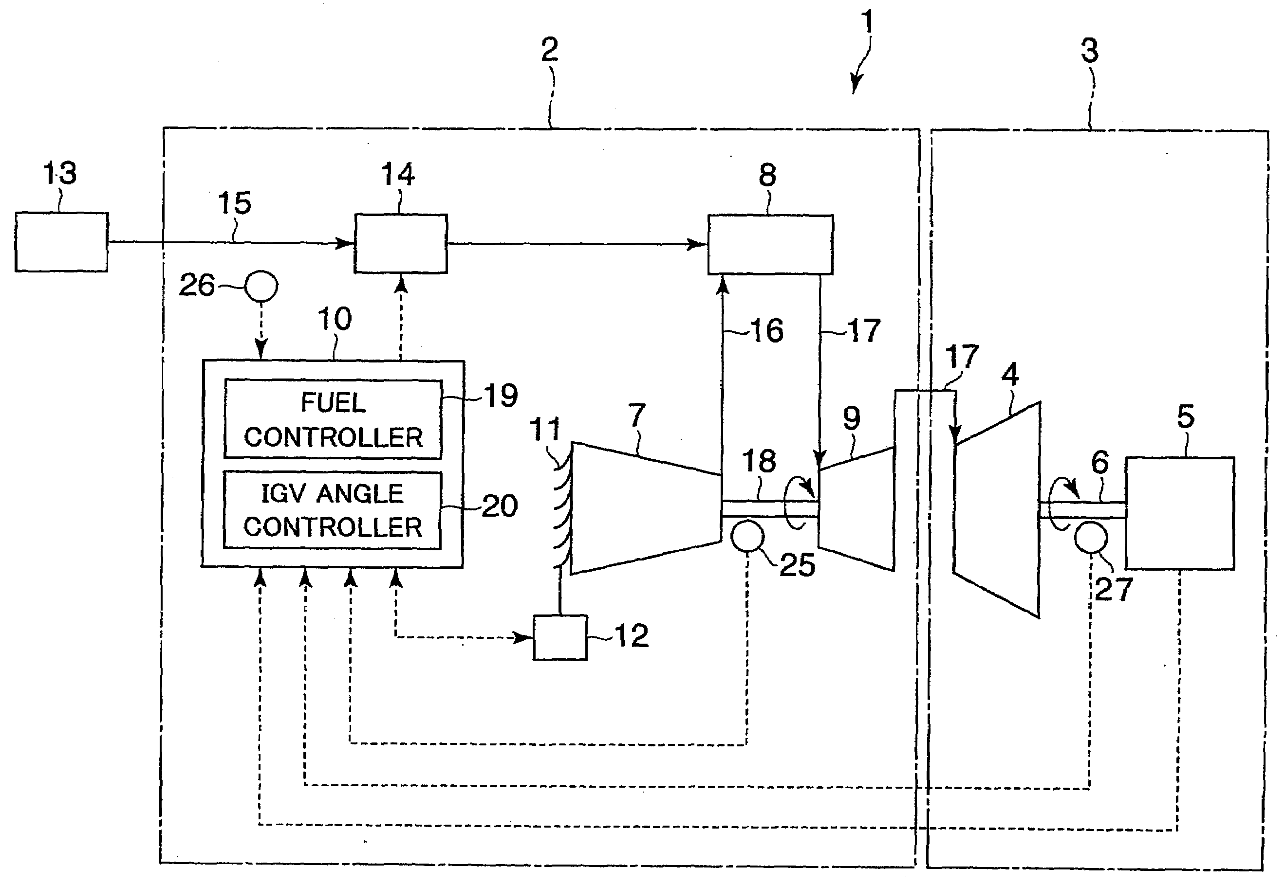
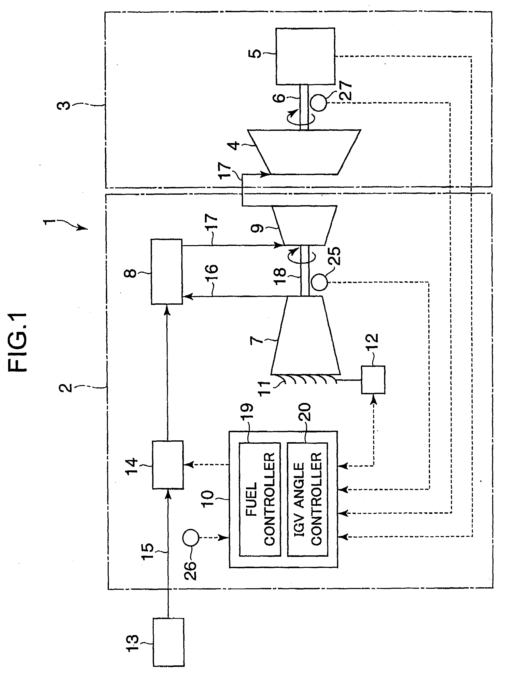
[0023]Hereunder, embodiments of the present invention will be described. A twin-shaft gas turbine 1 according to a first embodiment is shown in schematic form in FIG. 1. The twin-shaft gas turbine 1 includes a gas generator 2 and an output turbine 3.

[0024]The output turbine 3 includes a low-pressure turbine 4 and a load 5 as its major constituent elements, the load 5 being connected to the low-pressure turbine 4 via an output turbine shaft 6 which also operates as a rotor of the turbine 4.

[0025]The gas generator 2 includes a compressor 7, a combustor 8, a high-pressure turbine 9, and a gas generator control unit 10, as its major constituent elements.

[0026]The compressor 7 generates compressed air by letting air in from the atmosphere and compressing this air. Also, the compressor 7 has an inlet guide vane (IGV) 11 at its air inlet side. The IGV 11 is constructed to make its opening angle changeable via an IGV driver 12, thus changing an air inlet rate of the compressor 7.

[0027]The c...


PUM


Abstract

A twin-shaft gas turbine 1, which has a gas generator 2 including a compressor 7, a combustor 8, and a high-pressure turbine 9, is configured to make a first control mode and a second control mode selectively usable for control of the gas generator. In addition, in the first control mode, an IGV angle in the compressor is controlled in accordance with a corrected shaft rotation speed of the gas generator, and in the second control mode, the IGV angle is controlled to maintain a constant gas generator shaft rotation speed. Furthermore, the first control mode is used to start, to stop, and to operate the turbine under fixed or lower load conditions, and that the second control mode is used under operational states other than those to which the first control mode is applied.

Description

BACKGROUND OF THE INVENTION[0001]1. Field of the Invention[0002]The present invention relates generally to twin-shaft gas turbines, and more particularly, to controlling a gas generator in a twin-shaft gas turbine.[0003]2. Description of the Related Art[0004]Generally, a twin-shaft gas turbine includes a gas generator constituted by a compressor, a combustor, and a high-pressure turbine. This gas turbine also includes a low-pressure turbine (power turbine) connected to a load, with a gas generator shaft (a rotary shaft of the gas generator) being separated from a rotary shaft of the low-pressure turbine. In the gas generator, the compressor generates compressed air and supplies the compressed air to the combustor in which a fuel mixedly with the compressed air is then burned, thus combustion gases are generated. The combustion gases that have thus been produced by the combustor rotationally drive the high-pressure turbine to generate a driving force of the compressor. After this, th...

Claims


Application Information

Patent Timeline
Patent Type & Authority Applications(United States)
IPC IPC(8): F02C9/00F02C1/00
CPCF02C9/20F02C9/54F02C3/10F05D2270/304F05D2260/85F05D2260/96F05D2270/101F05D2270/024
Inventor NANATAKI, KENJISAITO, NOZOMIMURATA, HIDETARO
Owner MITSUBISHI POWER LTD
Why Eureka
Try Eureka