Pulverized coal concentration adjustment apparatus and pulverized coal combustion boiler
Active Publication Date: 2010-01-14
MITSUBISHI POWER LTD
View PDF7 Cites 22 Cited by
Summary
Abstract
Description
Claims
Application Information
AI Technical Summary
This helps you quickly interpret patents by identifying the three key elements:
Problems solved by technology
Method used
Benefits of technology
Benefits of technology
[0014]Thereby, pulverized coal fed to respective branch pipes positioned downstream of the pulverized coal distributor and respective pulverized coal burners can be uniformly distributed, so that it is possible to improve the combustion quality (reduction in NOx and unburned coal), thus enabling making boiler water tube temperatures uniform.
[0015]A pulverized coal combustion boiler according to the invention comprises a pulverized coal concentration adjustment apparatus, which can uniformly distribute pulverized coal, which is fed to
Problems solved by technology
In this manner, pulverized coal fed to the respective pulverized coal burners is distributed differently whereby there is a fear that a pul
Method used
Image
Click on the blue label to locate the original text in one second.
Reading with bidirectional positioning of images and text.
Examples
first embodiment
[0048]a pulverized coal concentration adjustment apparatus according to the invention will be described below with reference to FIGS. 1 to 4.
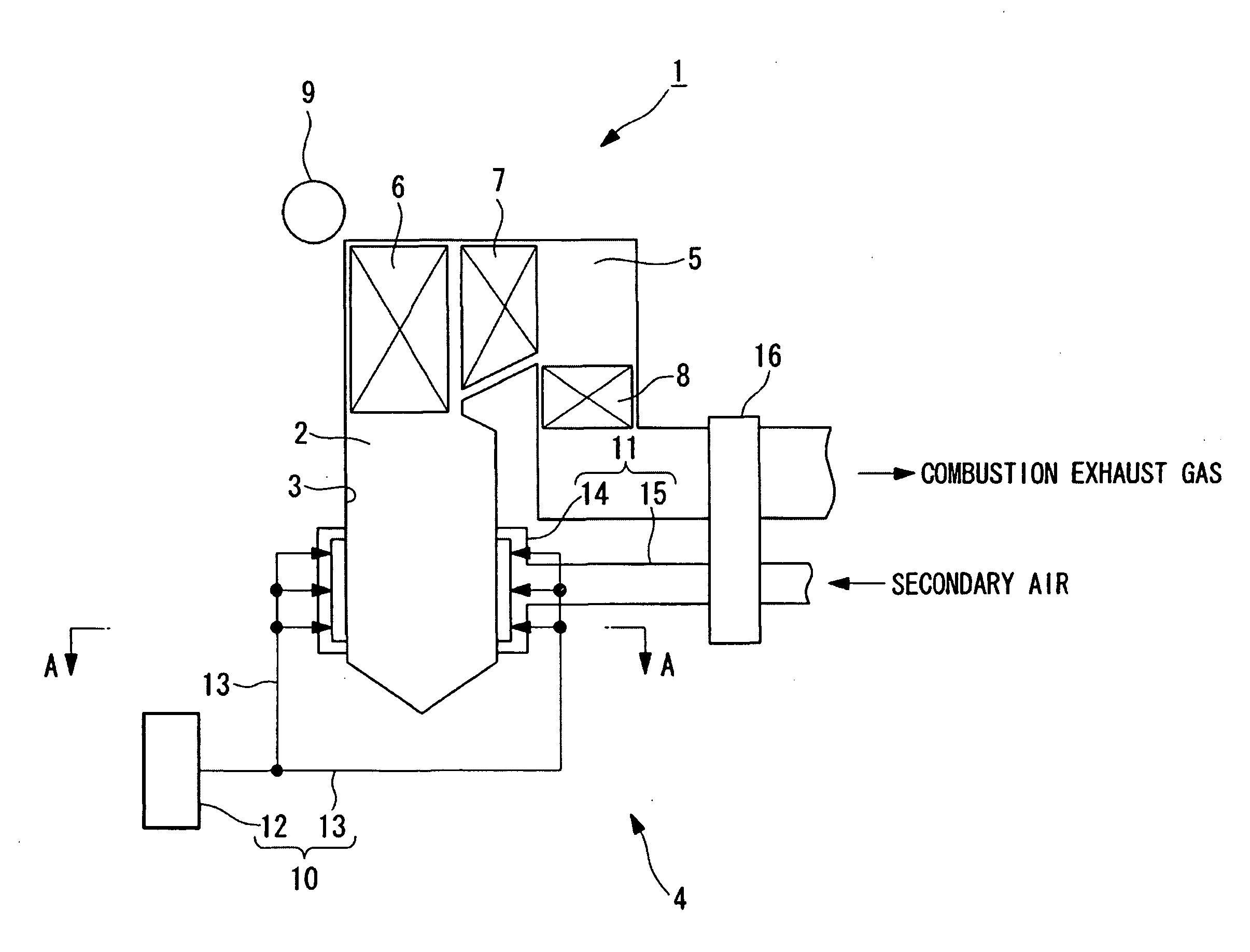
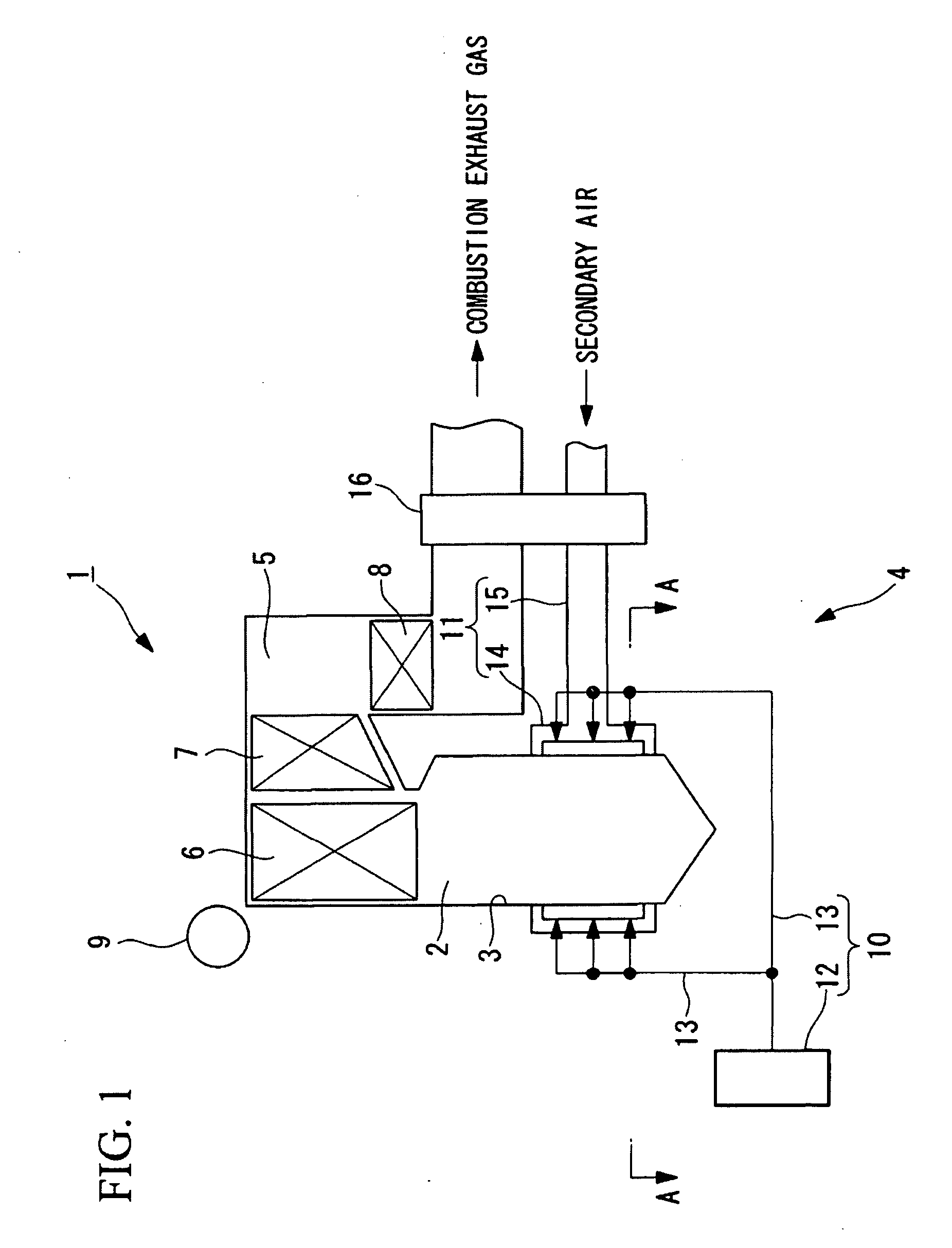
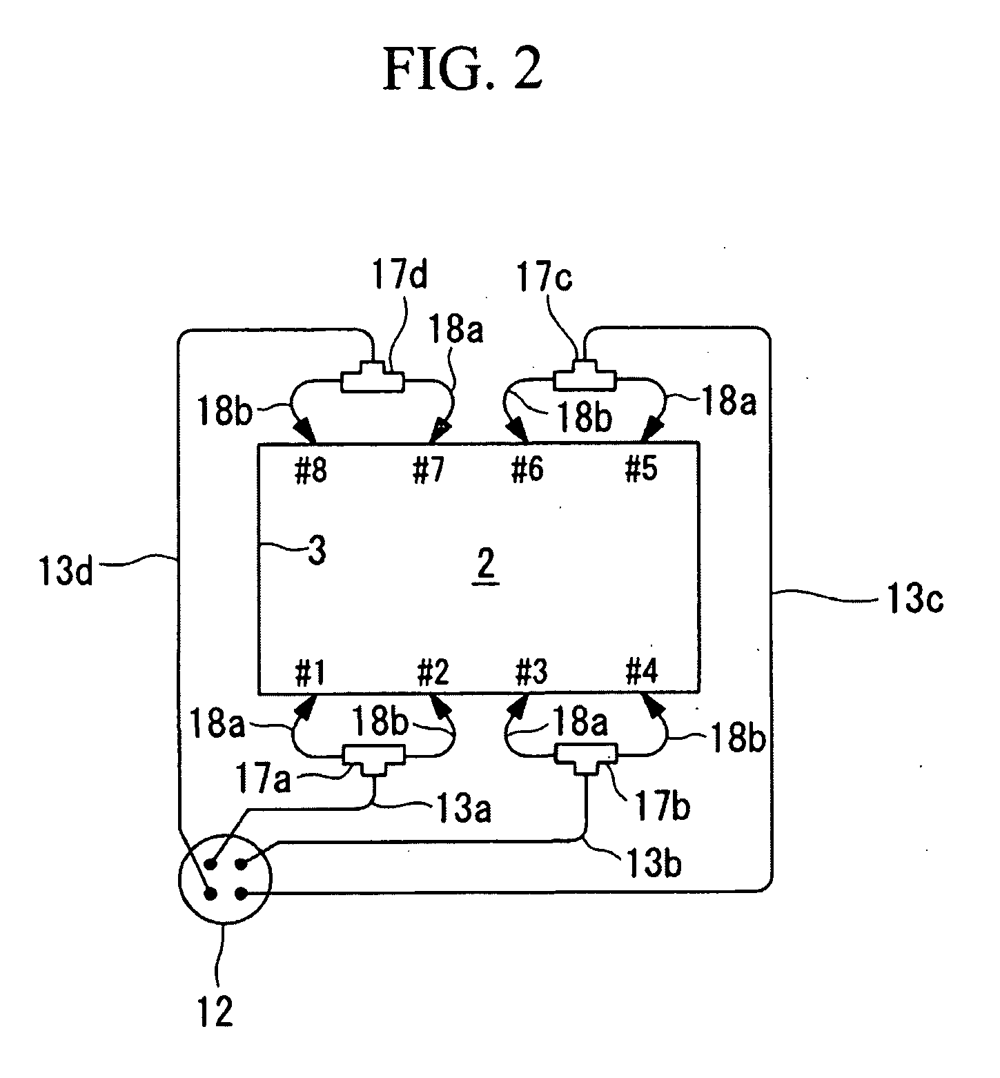
[0049]FIG. 1 is a block diagram showing a whole outline construction of a pulverized coal combustion boiler provided with a pulverized coal concentration adjustment apparatus according to the embodiment, FIG. 2 is a cross sectional view taken along the line A-A in FIG. 1, FIG. 3 is a perspective view showing the pulverized coal concentration adjustment apparatus, according to the embodiment, as viewed from a side of a pulverized coal pipe, and FIG. 4 is a perspective view showing a pulverized coal distributor, according to the embodiment, as viewed from a side of a kiln.
[0050]As shown in FIG. 1, a boiler 1 includes a kiln 2 mounted in a vertical direction, a combustion apparatus 4 mounted in a lower portion of a kiln wall 3 of the kiln 2, a gas flue 5 connected to an outlet of the kiln 2, a superheater 6 provided extending from an upper portion...
second embodiment
[0068]a pulverized coal concentration adjustment apparatus according to the invention will be described with reference to FIG. 5. FIG. 5 is a view showing a planar arrangement of the pulverized coal concentration adjustment apparatus according to the embodiment.
[0069]The pulverized coal concentration adjustment apparatus 31 according to the embodiment is different from that of the first embodiment in that instead of the kicker block 20 a pulverized coal pipe 33a, 33b, 33c, 33d is provided to arrange each of pulverized coal distributors 17a, 17b, 17c, 17d in a location 10D (D is an inside diameter of the pulverized coal pipe) distant from an elbow (bent portion) 32 of the pulverized coal pipe, more preferably, in the range of 3D to 5D from the elbow 32 of the pulverized coal pipe. Other constituent elements are the same as those of the first embodiment and so an explanation therefor is omitted herein.
[0070]In addition, the same members as those of the first embodiment are denoted by ...
third embodiment
[0074]a pulverized coal concentration adjustment apparatus according to the invention will be described with reference to FIG. 6. FIG. 6 is a perspective view showing the pulverized coal concentration adjustment apparatus, according to the embodiment, as viewed from a pulverized coal pipe.
[0075]The pulverized coal concentration adjustment apparatus 41 according to the embodiment is different from that of the first embodiment in that a ribbon screw 42 is provided instead of the kicker block 20. Other constituent elements are the same as those of the first embodiment and so an explanation therefor is omitted herein.
[0076]In addition, the same members as those of the first embodiment and the second embodiment are denoted by the same reference numerals as those of the latter.
[0077]As shown in FIG. 6, the ribbon screw 42 is a thin plate member, which divides a flow passage in a pulverized coal pipe 33a, 33b, 33c, 33d into two halves so as to make flow passage areas thereof substantially ...
PUM
Abstract
To achieve an improvement in concentration distribution in a vertical direction at an inlet of a pulverized coal distributor and uniformly distribute pulverized coal to respective pulverized coal burners. A pulverized coal distributor and a gas-particle flow adjustment device provided on an upstream side of the pulverized coal distributor and at a bottom in a pulverized coal pipe to adjust pulverized coal to branch pipes in concentration are provided, the gas-particle flow adjustment device comprises a plate-shaped member provided along a substantially overall width of the pulverized coal pipe to have a substantially rectangular shape as viewed in plan view, a front edge of the gas-particle flow adjustment device is mounted pivotally to a bottom surface of the pulverized coal pipe, and an angle formed between an upper surface of the gas-particle flow adjustment device and a bottom surface of the pulverized coal pipe can be automatically adjusted on the basis of signals from flow sensors mounted to the respective branch pipes.
Description
TECHNICAL FIELD[0001]The present invention relates to a pulverized coal concentration adjustment apparatus for adjustment of pulverized coal supplied to a plurality of pulverized coal burners mounted to a kiln wall of a pulverized coal combustion boiler, and a pulverized coal combustion boiler using the same.BACKGROUND ART[0002]As a pulverized coal combustion boiler, in which pulverized coal pulverized in a coal mill (mill apparatus) is supplied to a plurality of pulverized coal burners mounted to a kiln wall and burnt by the pulverized coal burners, one disclosed in, for example, Patent Citation 1 is known.[0003]Patent Citation 1: Japanese Unexamined Patent Application, Publication No. 2006-102666DISCLOSURE OF INVENTION[0004]By the way, in such pulverized coal combustion boiler, pulverized coal pulverized in a coal mill is pneumatically conveyed in a pulverized coal pipe. Since pulverized coal is large in mass as compared with an air and has a tendency of gravitational sedimentatio...
Claims
Application Information
Patent Timeline
Application Date:The date an application was filed.
Publication Date:The date a patent or application was officially published.
First Publication Date:The earliest publication date of a patent with the same application number.
Issue Date:Publication date of the patent grant document.
PCT Entry Date:The Entry date of PCT National Phase.
Estimated Expiry Date:The statutory expiry date of a patent right according to the Patent Law, and it is the longest term of protection that the patent right can achieve without the termination of the patent right due to other reasons(Term extension factor has been taken into account ).
Invalid Date:Actual expiry date is based on effective date or publication date of legal transaction data of invalid patent.

