Electrostatic coating apparatus

Active Publication Date: 2010-01-14
NAT TAIWAN UNIV
View PDF5 Cites 15 Cited by
  • Summary
  • Abstract
  • Description
  • Claims
  • Application Information

AI Technical Summary

Benefits of technology

[0009]According to the electrostatic coating apparatus of the invention, the thickness of the coating layer ca

Problems solved by technology

Thus, the material is wasted, and the environmental problem is caused because a lot of solvents have to be used for rinsing.
Although the dip coating method can form the coating layer having the thickn

Method used


Image

  • Electrostatic coating apparatus
  • Electrostatic coating apparatus
  • Electrostatic coating apparatus

Examples


Example

[0015]The present invention will be apparent from the following detailed description, which proceeds with reference to the accompanying drawings, wherein the same references relate to the same elements.

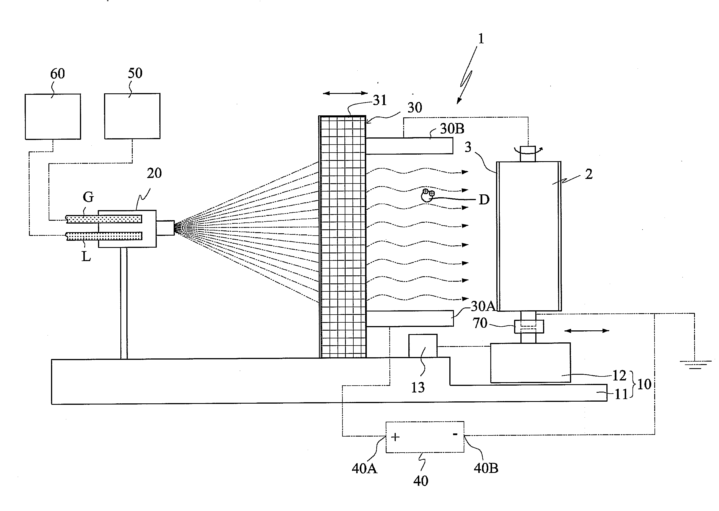
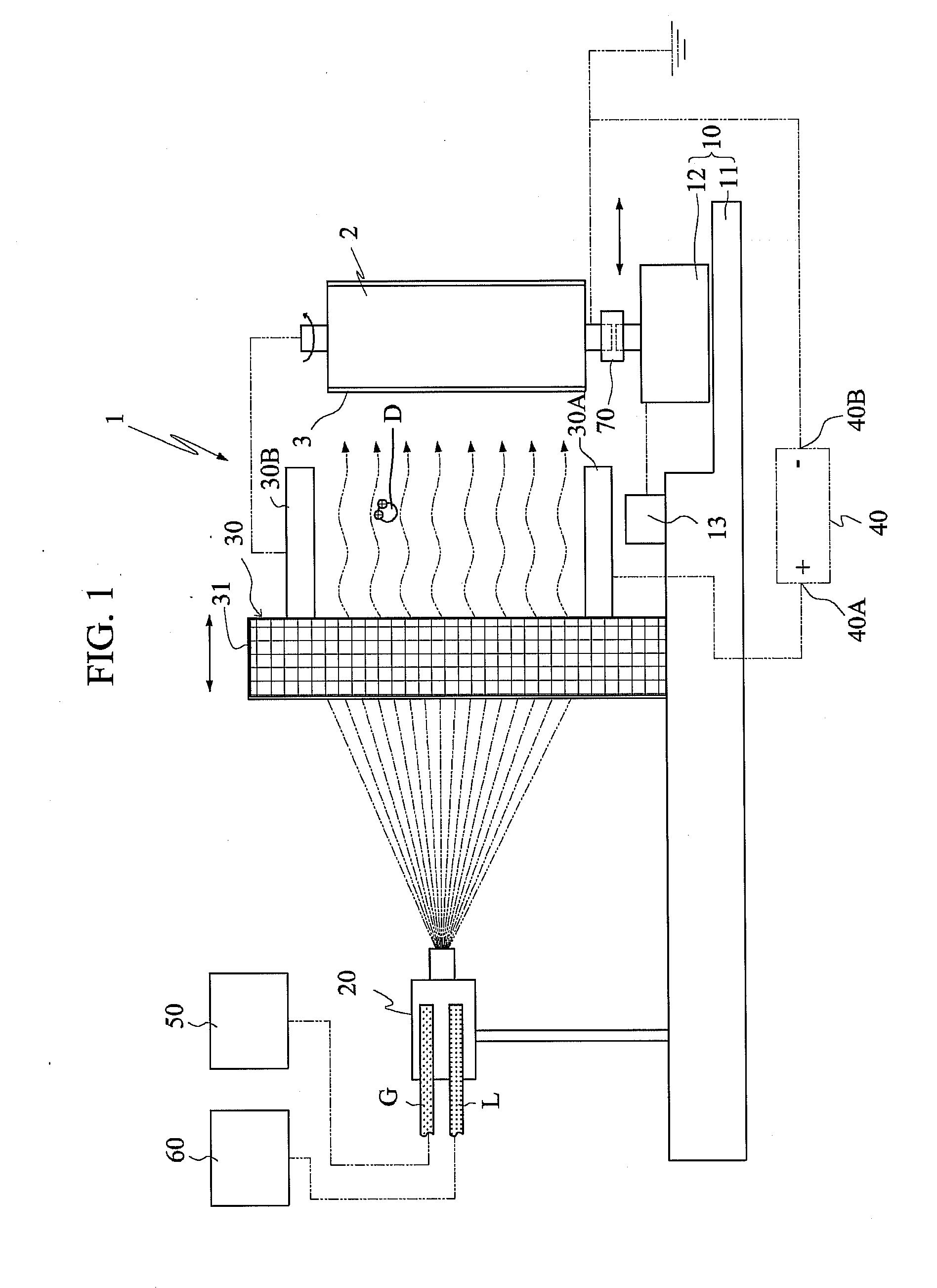
[0016]The principle of electrostatic coating is mainly based of the law of conservation of charge, which means that the free charges may be transferred between objects and can neither be increased nor diminished. When the object is electrified to have the same positive and negative charges, the object has the charge neutrality. When the positive charges of the object or the negative charges of the object are not the same, the object becomes a charged body. Thus, the invention provides an electrostatic coating apparatus capable of making the fog drops of atomized photoresist or the fog drops of other materials pass through an electric field. The so-called electric field represents a spatial field of force around each charge or a group of charges and has the unit of measurement (Newton / ...


PUM


Abstract

An electrostatic coating apparatus for coating an object includes a base module, a nozzle, an electric field generator and a power supply. The object is mounted on the base module. The nozzle receives gas and liquid and ejects the gas and the liquid. The electric field generator mounted on the base module generates an electric field. The power supply has a first pole electrically connected to a first pole of the electric field generator, and a second pole electrically connected to the object and a second pole of the electric field generator such that the electric field is generated in the electric field generator and the atomized liquid passing through the electric field generator is charged and absorbed onto the object to form a coating layer on the object.

Description

[0001]This application claims priority of No. 097126228 filed in Taiwan R.O.C. on Jul. 11, 2008 under 35 USC 119, the entire content of which is hereby incorporated by reference.BACKGROUND OF THE INVENTION[0002]1. Field of Invention[0003]The invention relates to an electrostatic coating apparatus, and more particularly to an electrostatic coating apparatus for coating an object according to an electrostatic principle.[0004]2. Related Art[0005]At present, the coating methods adopted in the opto-electronic and semiconductor industry include a spin coating method, a roller coating method and a dip coating method. The spin coating method is mainly to coat a photoresist onto a substrate, wherein the availability of the photoresist is about 10%, so the other 90% of the photoresist are treated as a waste material. Thus, the material is wasted, and the environmental problem is caused because a lot of solvents have to be used for rinsing. The roller coating method is to coat the material ont...

Claims


Application Information

Patent Timeline
IPC IPC(8): B05C11/00
CPCB05B5/03B05B5/082H05K3/0091B05B5/10B05B5/14B05B5/087
Inventor YANG, SEN-YEUHUANG, TZU-CHIENLAI, HSIN-CHUNLU, GUAN-NAN
Owner NAT TAIWAN UNIV
Why Eureka
Try Eureka