Lubricating apparatus for a dosing system for cylinder lubrication oil and method for dosing cylinder lubricating oil

Active Publication Date: 2010-01-14
HANS JENSEN LUBRICATORS
View PDF7 Cites 24 Cited by
  • Summary
  • Abstract
  • Description
  • Claims
  • Application Information

AI Technical Summary

Benefits of technology

[0058]According to the present invention it will be possible to provide only one monitoring sensor for detecting the displacement of the distributor plate. Such a sensor may in principle be disposed centrally in relation to the distributor plate.
[0059]Alternatively, several sensors may be used distributed across the face of the distributor plate, so as to ensure that the planned linear movement is performed.
[0060]If a plurality of sensors distributed across the face of the distributor plate are used, it is possible at the same time to ascertain if a true linear displacement of the entire distributor plate has been performed, or if the distributor plate tilts during the displacement. This may e.g. be the case if one or more of the hydraulic pistons fail. In other words, by using several sensors there may be performed detection that can be used for determining possible functional failure in one or more of the hydraulic pistons.
[0061]Typically, there will be one lubricating apparatus per cylinder. However, it is possible to section a lubricating apparatus so that it is po

Problems solved by technology

Driving the lubricating apparatuses synchronously with the engine speed is electronically feasible, but extensive and costly.
Changing the dosed cylinder lubricating oil portion is, however, more difficult to control.
This

Method used


Image

  • Lubricating apparatus for a dosing system for cylinder lubrication oil and method for dosing cylinder lubricating oil
  • Lubricating apparatus for a dosing system for cylinder lubrication oil and method for dosing cylinder lubricating oil
  • Lubricating apparatus for a dosing system for cylinder lubrication oil and method for dosing cylinder lubricating oil

Examples


first embodiment

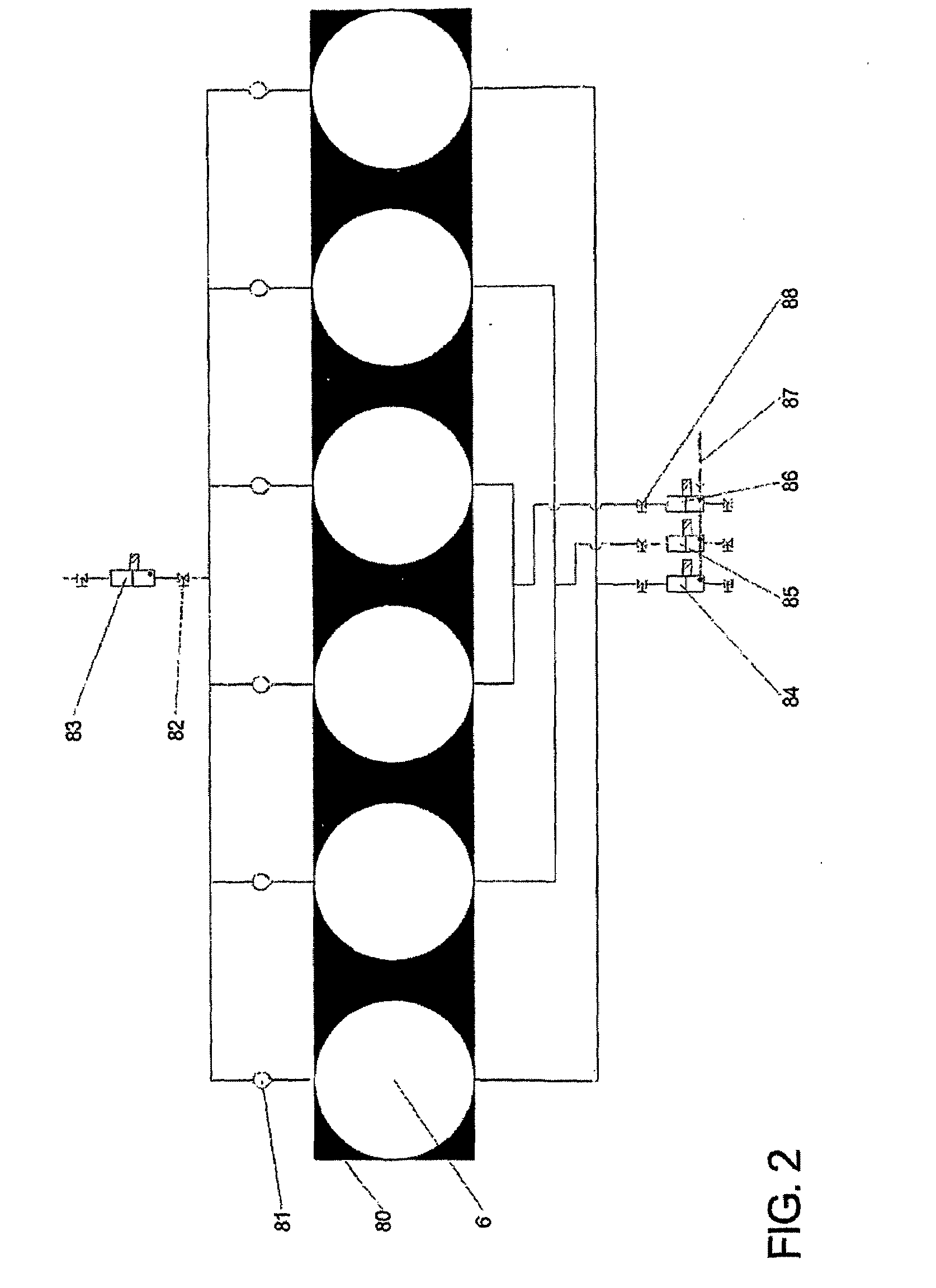
[0110]FIG. 2 shows a schematic drawing of a first embodiment with an elongated distributor plate;

second embodiment

[0111]FIG. 3 shows a schematic drawing of a second embodiment with a circular distributor plate;

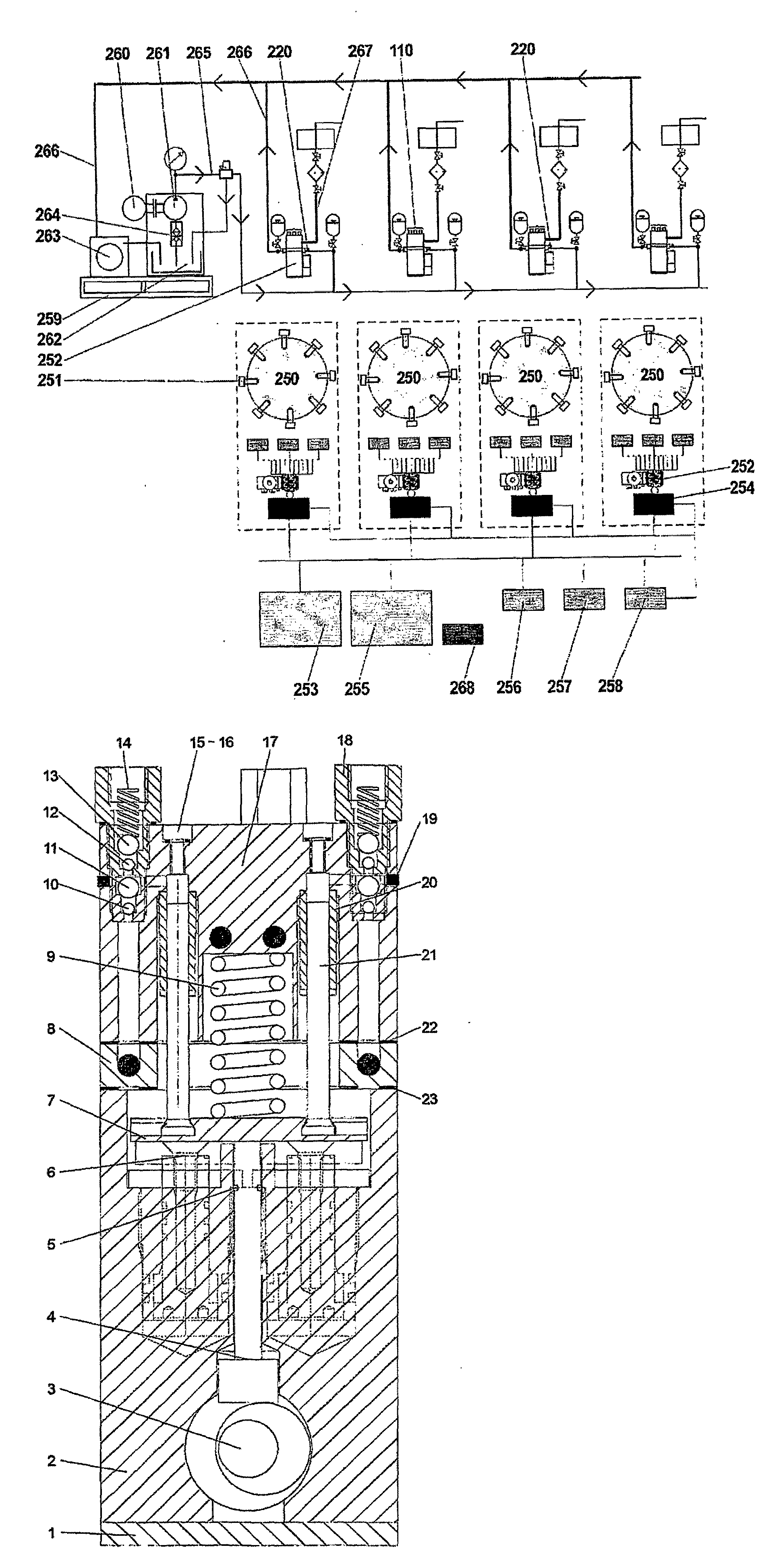
[0112]FIG. 4 shows a sectional view through an embodiment of a lubricating apparatus according to the invention;

[0113]FIG. 5 shows a sectional view through a lubricating apparatus shown at right angle to the section in FIG. 4;

[0114]FIG. 6 shows a plan view of the lubricating apparatus shown in FIGS. 4 and 5;

[0115]FIG. 7 shows a plan view of the base block shown in FIG. 4;

[0116]FIG. 8 shows a section through the base block shown in FIG. 7 according to the arrows VII-VII;

[0117]FIG. 9 shows an alternative embodiment of a base block with common stroke stop as well as stroke limitation;

[0118]FIG. 10 shows a detail of the distributor plate shown in FIG. 4;

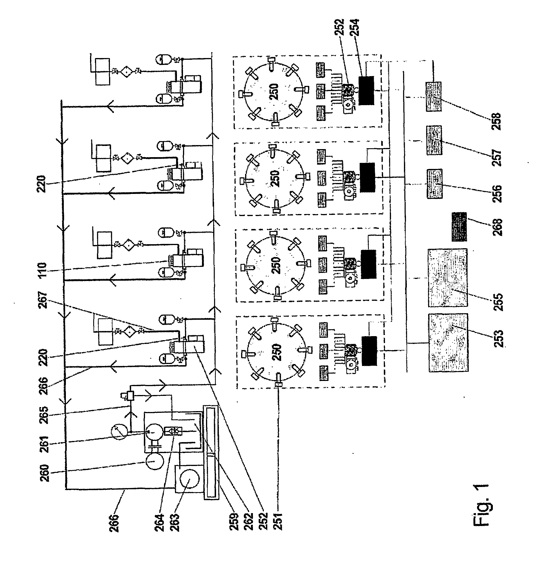
[0119]FIG. 11 shows a schematic drawing corresponding to the schematic overview shown in FIG. 1 of a system according to the invention;

[0120]FIG. 12 shows a sectional view through a further embodiment of a lubricating apparatus according to th...


PUM


Abstract

There is disclosed a method and a hydraulic lubricating apparatus for dosing cylinder lubricating oil. The dosing system includes a supply line and a return line connected with the lubricating apparatus via each one or more valves for supplying hydraulic oil, a central hydraulic oil feed pump connected with hydraulic cylinders, each having a hydraulic piston and which may be subjected to pressure by hydraulic oil via the supply line, a number of injection units corresponding to a multiple of the cylinder number in the engine and which are connected with each their dosing cylinder with a dosing piston and a supply line for cylinder lubricating oil. In order to provide a system which is reliable and cheap and where there is no risk of disruptions, even if a hydraulic cylinder fails, the lubricating apparatus is designed with a distributor plate which at one side is in contact with the dosing pistons and which at its other side is in contact with two or more hydraulic pistons for displacing the distributor plate for activating the dosing pistons.

Description

FIELD OF THE INVENTION[0001]The present invention concerns a hydraulic lubricating apparatus for a dosing system for cylinder lubricating oil, e.g. in marine engines, the dosing system including[0002]a supply line and a return line connected with the lubricating apparatus via one or more valves for supplying hydraulic oil;[0003]a central hydraulic oil feed pump which via the supply line is connected with hydraulic cylinders each having a hydraulic piston and which may be subjected to pressure by hydraulic oil;[0004]a number of injection units corresponding to a multiple of the cylinder number in the engine, and which are connected with each their dosing cylinder with a dosing piston;[0005]a supply line for cylinder lubricating oil;[0006]a distributor plate which at one side is in contact with the dosing pistons.[0007]Moreover, the invention concerns a method for a dosing cylinder lubricating oil, e.g. in marine engines, the method including:[0008]supplying hydraulic oil pressure via...

Claims


Application Information

Patent Timeline
IPC IPC(8): F01M1/04B63H21/38
CPCF01M1/08F01M2001/083F16N13/04F02B61/04F16N25/00F16N2260/00F16N13/16F01M1/16F01M3/04F01M1/02
Inventor AAMAND, JAN
Owner HANS JENSEN LUBRICATORS
Why Eureka
Try Eureka