Chain sprocket with increased load capacity

a chain sprocket and load capacity technology, applied in the direction of driving chains, gearing, hoisting equipment, etc., can solve the problems of reduced thickness of chain links and inability of chain sprockets to utilize chains to a higher degree, and achieve the effect of improving the running of vertical chain links

Active Publication Date: 2010-01-14
KONECRANES GLOBAL
View PDF10 Cites 6 Cited by
  • Summary
  • Abstract
  • Description
  • Claims
  • Application Information

AI Technical Summary

Benefits of technology

[0031]To improve the running of the vertical chain link onto and off of the load-receiving tooth flank, the load-receiving tooth flank preferably transitions in the vicinity of the crest of the tooth into a bevel. The bevel can have a curved or flat surface. The height of the bevel, measured in the radial direction of the tooth, preferably lies between 0.1 and 2 mm, preferably between 0.2 and 1.5 mm.

Problems solved by technology

The relative motion between the chain links causes frictional wear, with the result that the thickness of the chain link is reduced in the areas experiencing the friction.
The known chain sprocket is thus not capable of utilizing the chain to a higher degree than that which corresponds to the standards according to the safety limit values.

Method used


Image

  • Chain sprocket with increased load capacity
  • Chain sprocket with increased load capacity
  • Chain sprocket with increased load capacity

Examples


Embodiment Construction

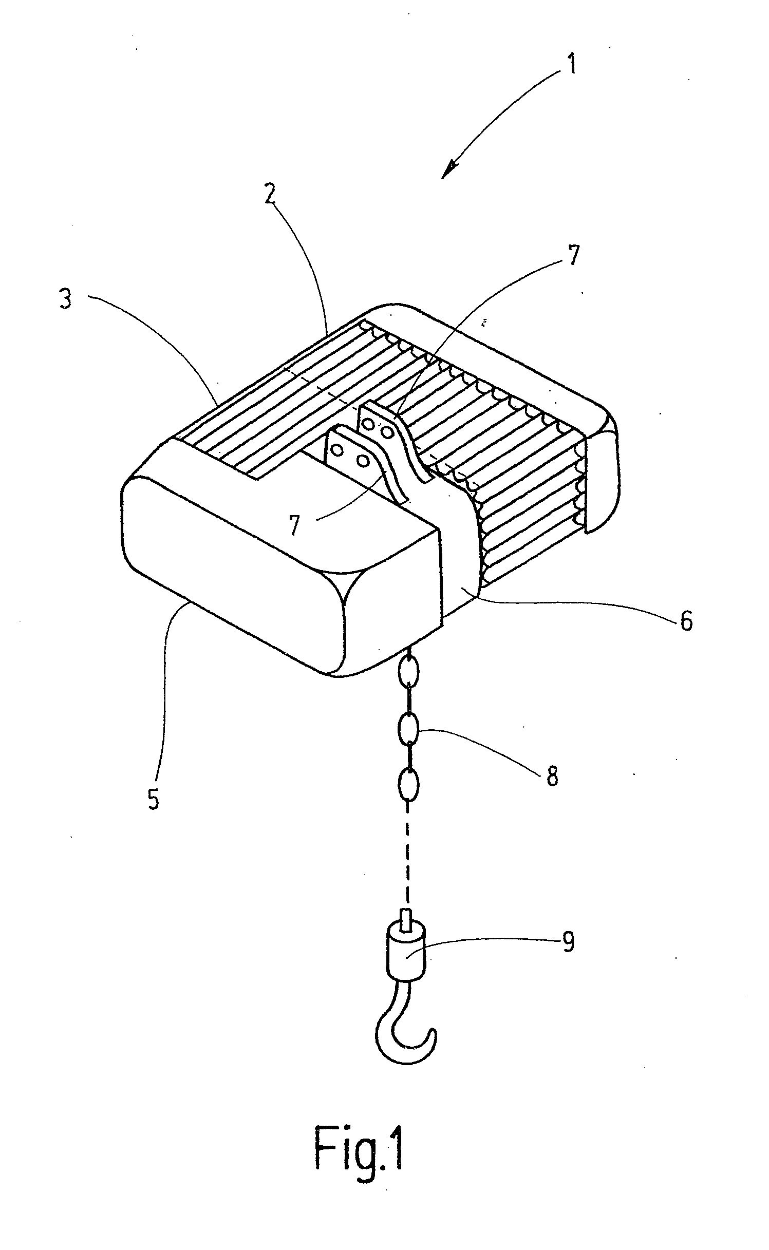
[0043]Referring to FIG. 1 of the drawings, a chain hoist 1 is shown in a simplified perspective representation as an exemplary application of the present invention. The chain hoist 1 has a roughly block-shaped gear assembly housing 2, onto one end face of which an electric motor 3 in the form of asynchronous motor is flange-mounted. Both the gear assembly housing 2 and the motor 3 are provided with continuous cooling ribs, as can be seen in FIG. 1. A cover 5 containing the controller or essential parts of the controller is provided on the motor 3 on the side remote from the gear assembly housing 2. A chain sprocket housing 6, from the upper side of which brackets 7 project that serve for suspension of the chain hoist 1, is situated between the controller cover 5 and the opposing end face of the gear assembly housing. A round link chain 8, on the free end of which a hook 9 is mounted, extends down from the chain sprocket housing 6.

[0044]As can be appreciated from FIG. 1, only a force...


PUM


Abstract

A chain sprocket for link chains, for example, round link chains or profiled steel chains, has chain pockets for horizontal chain links. Chain pockets for vertical chain links are also provided. The chain pockets for the vertical chain links are separated from one another by teeth. The tooth flank surface of the tooth that a vertical chain link contacts under the effect of a load is dimensioned and profiled in a special manner. The dimensioning is such that up to a defined chain load the vertical chain link does not contact the tooth flank with its nose. A contact between the tooth flank surface and the nose of the respective chain link occurs only above a defined chain load.

Description

CROSS-REFERENCE TO RELATED APPLICATIONS[0001]This patent application is the national phase of PCT / EP2007 / 004670, filed May 25, 2007, which claims the benefit of German Patent Application No. DE 10 2006 036 162.8, filed Aug. 1, 2006.FIELD OF THE INVENTION[0002]The present invention relates generally to a chain sprocket for driving link chains.BACKGROUND OF THE INVENTION[0003]So-called round link chains are composed of concatenated individual round links. Respective adjacent chain links are rotated by 90° with respect to one another relative to the longitudinal axis of the chain. Each chain link of a round link chain consists of a bent wire section, the free ends of which are butt-welded to one another.[0004]In a plan view onto the flat side, the chain link consists of two straight mutually parallel sections, both transitioning at each end into semicircular arcs. The radius of the two semicircular arcs corresponds to the center separation of the straight sections. The projection of su...

Claims


Application Information

Patent Timeline
Patent Type & Authority Applications(United States)
IPC IPC(8): B66D1/30
CPCF16H55/303B66D3/26F16H55/00F16H55/02F16H55/30
Inventor WEINGARTNER, JURGENFINZEL, MANFREDDIETRICH, VOLKER
Owner KONECRANES GLOBAL
Why Eureka
Try Eureka