Method for modernizing a technical system and an appropriate drive element

a technology of drive elements and technology, applied in the direction of dynamo-electric converter control, program control, instruments, etc., can solve the problems of increasing the susceptibility to faults, outdated technology, and no longer up to da

Inactive Publication Date: 2010-01-14
SIEMENS AG
View PDF7 Cites 0 Cited by
  • Summary
  • Abstract
  • Description
  • Claims
  • Application Information

AI Technical Summary

Benefits of technology

[0006]An object of the present invention is therefore to specify a method and an appropriate drive element which allows a technical system to be modernized in a way which is favorable from a financial standpoint as well as being advantageous from a technical standpoint.

Problems solved by technology

Many technical systems, especially production systems for manufacturing products on a production line system (e.g. paper, textiles, plastic foils, metal foils) have drive technologies which are no longer up to date, e.g. analog technology-based drives.
This outdated technology has serious disadvantages since it exhibits an increased susceptibility to faults because it is getting older and as a result of external influences for example, an inability to repeat operations accurately and only limited diagnostic facilities.
This results in unsatisfactory system availability, high scrap quotas and high failure costs.
However such modernizing involves a high overall expenditure, since modifications will be required as a rule for an upgrading step both in the new, modernized part of the system as well in the existing system parts, especially at the existing automation level, to enable the new and old parts of the system to communicate with each other.
Furthermore it is not possible with this process to implement a contemporary drive and automation concept which increases productivity while an old part of the system is still present.
An implementation of the concept in the last step, i.e. for upgrading of the last part of the system, can also no longer be implemented at acceptable expense.
Consequently all conventional approaches to solutions are not optimum from either a technical or a financial standpoint.
Many system operators therefore put up with the disadvantages of the existing system and forego modernization of the complete system.

Method used


Image

  • Method for modernizing a technical system and an appropriate drive element
  • Method for modernizing a technical system and an appropriate drive element
  • Method for modernizing a technical system and an appropriate drive element

Examples


Embodiment Construction

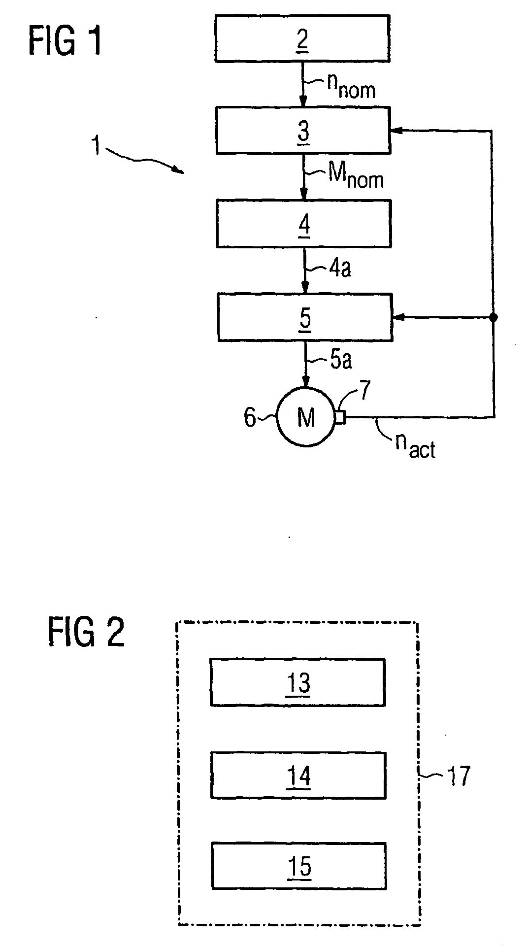
[0028]FIG. 1 shows a previous (old) drive element 1 of a technical system, e.g. of a production system for paper making. The drive element 1 features a drive motor 6, a power element 5 feeding the motor 6 via a feed connection 5a, a torque controller 4 controlling the power element 5 via a control connection 4a and a speed controller 3 which specifies to the torque controller 4 a nominal torque value Mnom with regard to the motor torque. An actual speed value nact required for control is recorded by a speed encoder 7 on the motor 6 and made available to the speed controller 3 and to the power element 5. The drive element 1 is subordinate to an (old) drive automation 2 which specifies a nominal speed value nnom to the speed controller 3. Both the drive element 1 and also the higher-ranking automation system 2 are essentially embodied in analog technology or in outdated digital technology and the drive motor 6 is also embodied in outdated direct current technology, so that the require...


PUM


Abstract

One embodiment relates to modernizing a technical system, in particular a producing system with the aim of obtaining economic and technical advantages. The technical system comprises at least one drive mechanism provided with at least one drive motor powered by a power element, a torque controller controlling the power element and a speed controller prescribing the nominal value of the torque (Msoll) for the torque controller. When the determination of the nominal value of the torque (Msoll) for the torque controller by the speed controller is deactivated, a standard drive element is available. The drive element comprises at least one speed controller, a torque controller and a power element. The nominal value of the torque (Msoll) of the torque controller of the drive motor is determined by a speed controller of the standard drive element.

Description

CROSS REFERENCE TO RELATED APPLICATIONS[0001]This application is the US National Stage of International Application No. PCT / EP2004 / 004911, filed May 7, 2004 and claims the benefit thereof. The International Application claims the benefits of German application No. 10320826.7 DE filed May 8, 2003, both of the applications are incorporated by reference herein in their entirety.FIELD OF INVENTION[0002]The invention relates to a method for modernizing a technical system, especially a production system as well as a drive element.BACKGROUND OF INVENTION[0003]Many technical systems, especially production systems for manufacturing products on a production line system (e.g. paper, textiles, plastic foils, metal foils) have drive technologies which are no longer up to date, e.g. analog technology-based drives. This outdated technology has serious disadvantages since it exhibits an increased susceptibility to faults because it is getting older and as a result of external influences for example...

Claims


Application Information

Patent Timeline
Patent Type & Authority Applications(United States)
IPC IPC(8): H02P7/00G05B19/042H02P21/00
CPCG05B19/042
Inventor HAAKS, STEFANMICHAELIS, GERDWEGNER, CHRISTIAN-MARIUS
Owner SIEMENS AG
Why Eureka
Try Eureka