Wire-grid polarizer, method for producing the wire-grid polarizer, retardation film and liquid crystal display device using the retardation film

Inactive Publication Date: 2010-01-14
NIPPON OIL CORP
View PDF5 Cites 22 Cited by
  • Summary
  • Abstract
  • Description
  • Claims
  • Application Information

AI Technical Summary

Benefits of technology

[0007]The present invention has been made in consideration of the above-described problems in the conventional techniques. An object of the present invention is to provide a method for producing a wire-grid polarizer, enabling efficient and reliable production of a wire-grid polarizer which has a metal grating with a sufficiently short grating period and which can be used as a polarizer for a visible region; a wire-grid polarizer obtained according to the method; a retardation film including the wire-grid polarizer on its film surface; and a liquid crystal display device using the retardation film.
[0008]The present inventors have earnestly studied in order to achieve the above object. As a result, the inventors have revealed that, by a method for producing a wire-grid polarizer, comprising the steps of: preparing a resin film including a concave part formed thereon, the concave part having a grating pattern of submicron size, the resin film having a visible-light transmittance of 80% or more; filling the concave part with an electroconductive nano-material having an average diameter equal to or smaller than ½ of an average linewidth of the concave part; and removing the electroconductive nano-material which has not been filled into the concave part, it is made possible to efficiently and reliably produce a wire-grid polarizer which has a metal grating with a sufficiently short grating period and which can be used as a polarizer for a visible region. This discovery has led the inventors to complete the present invention.
[0021]According to the present invention, it is possible to provide: a method for producing a wire-grid polarizer, enabling efficient and reliable production of a wire-grid polarizer which has a metal grating with a sufficiently short grating period and which can be used as a polarizer for a visible region; a wire-grid polarizer obtained according to the method; a retardation film including the wire-grid polarizer on its film surface; and a liquid crystal display device using the retardation film.

Problems solved by technology

However, a method for producing a wire-grid polarizer as described in Document 1 requires complicated steps, particularly a step of depositing a metal that requires a vacuum process.
Accordingly, this method is not suitable as an industrial production method of a wire-grid polarizer having a large area.
Accordingly, this method is complicated in terms of the process, and also has a problem in the mass productivity.

Method used


Image

  • Wire-grid polarizer, method for producing the wire-grid polarizer, retardation film and liquid crystal display device using the retardation film
  • Wire-grid polarizer, method for producing the wire-grid polarizer, retardation film and liquid crystal display device using the retardation film
  • Wire-grid polarizer, method for producing the wire-grid polarizer, retardation film and liquid crystal display device using the retardation film

Examples


example 1

[0052]Firstly, prepared were a silica-glass mold (produced by NTT-AT Nanofabrication Corporation, product name “NIM-80L RESO”), a UV curable resin (produced by TOAGOSEI CO., LTD., product name “UV-3400”), and a support film (produced by Fuji Photo Film Co., Ltd., product name “triacetylcellulose (TAC) film”, film thickness: 80 μm).

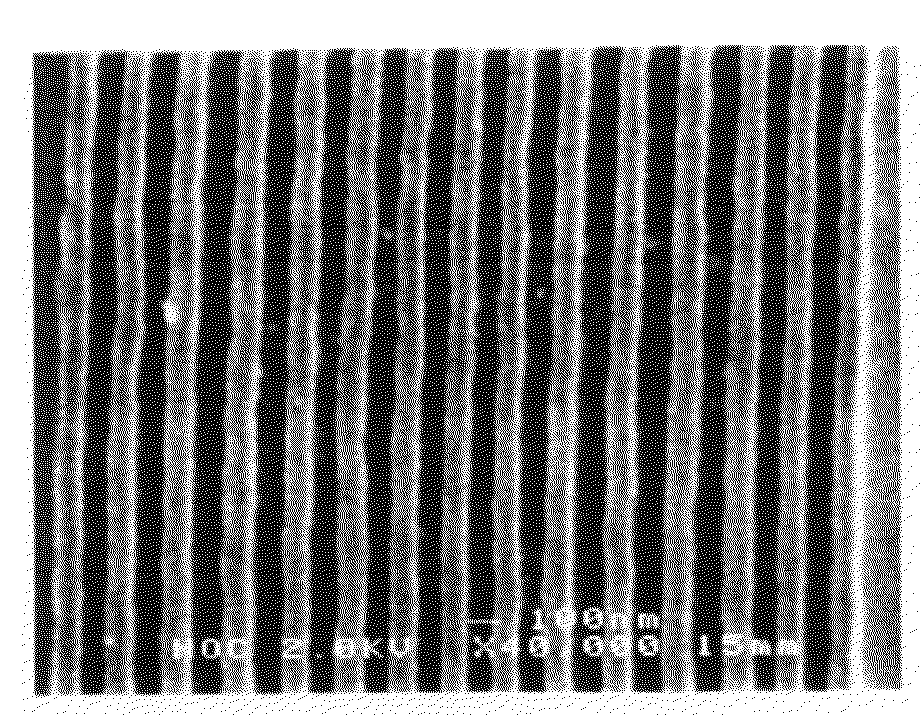
[0053]Then, several droplets of the UV curable resin were added onto the silica-glass mold including a concave part formed thereon, the concave part having a grating pattern with a grating period of 200 nm and a linewidth of 100 nm. After the resultant mold was covered with the support film, the support film was rubbed with a handroller. Thereby, the UV curable resin was spread on the silica-glass mold uniformly. Subsequently, the UV curable resin was irradiated with an ultraviolet ray of 600 mJ / cm2 from the support film side and hardened. Thereby, a coating film of the UV curable resin in which a concave part having a grating pattern was formed was caused...

example 2

[0056]A resin film and a wire-grid polarizer were obtained in the same manner as that in Example 1 except that the UV curable resin was added dropwise onto a silica-glass mold including a concave part formed thereon, the concave part having a grating pattern with a grating period of 400 nm and a linewidth of 200 nm. Note that, in the obtained resin film, a concave part having a grating pattern with a grating period of 400 nm and a linewidth of 200 nm was formed.

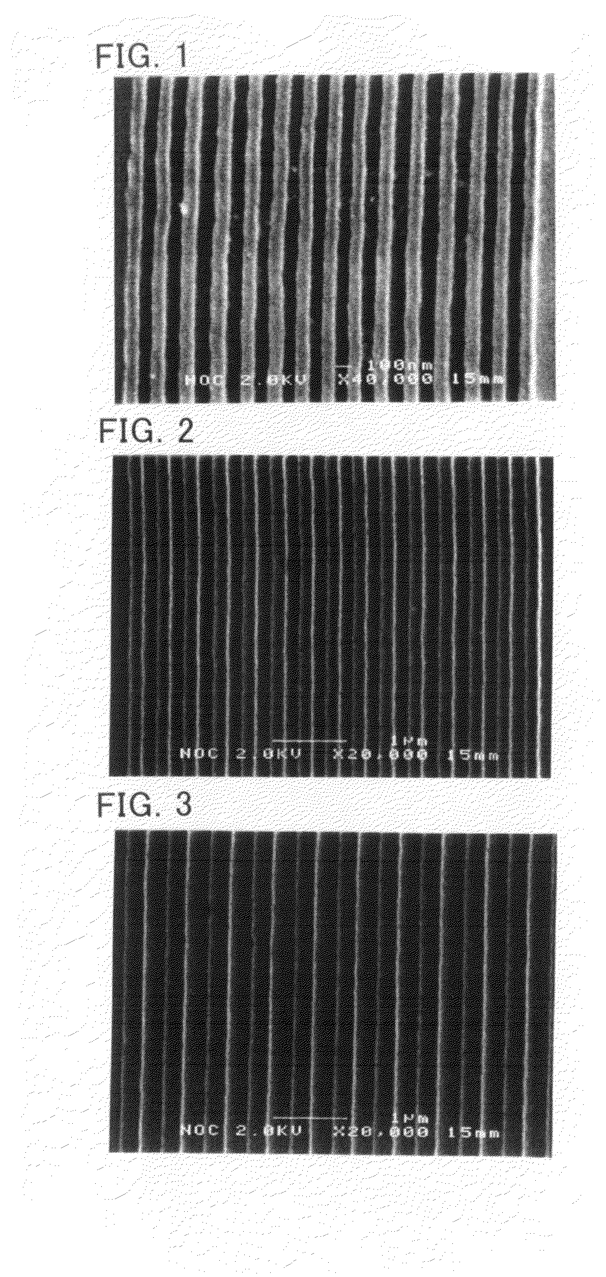
[0057]FIG. 2 shows a scanning electron microphotograph of the obtained wire-grid polarizer. As shown in FIG. 2, it was observed that the obtained wire-grid polarizer had a metal grating with a grating period of 400 nm and a linewidth of 200 nm.

example 3

[0058]A resin film and a wire-grid polarizer were obtained in the same manner as that in Example 1 except that the UV curable resin was added dropwise onto a silica-glass mold including a concave part formed thereon, the concave part having a grating pattern with a grating period of 600 nm and a linewidth of 300 nm. Note that, in the obtained resin film, a concave part having a grating pattern with a grating period of 600 nm and a linewidth of 300 nm was formed.

[0059]FIG. 3 shows a scanning electron microphotograph of the obtained wire-grid polarizer. As shown in FIG. 3, it was observed that the obtained wire-grid polarizer had a metal grating with a grating period of 600 nm and a linewidth of 300 nm.

[0060]

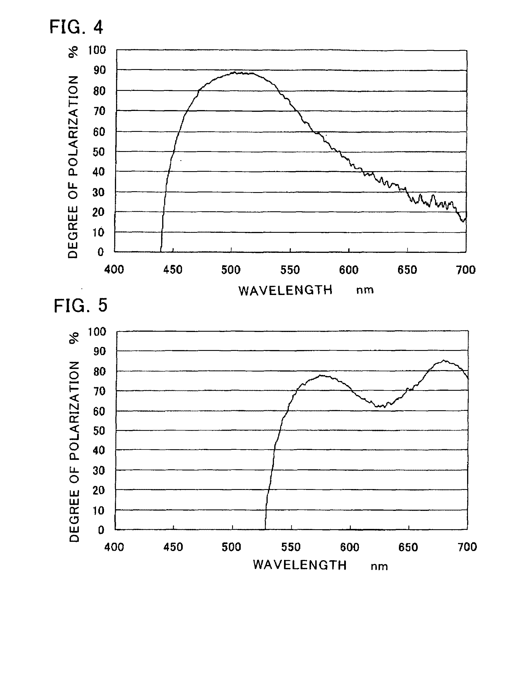
[0061](i) Method of Measuring Degree of Polarization

[0062]The wire-grid polarizers obtained in Examples 1 to 3 were used as samples. The microspectroscope used here was a transmission polarizing microscope (produced by Minolta Co., Ltd.) equipped with a spectroscope (produced by H...


PUM

PropertyMeasurementUnit
Nanoscale particle sizeaaaaaaaaaa
Transmittivityaaaaaaaaaa

Abstract

A method for producing a wire-grid polarizer includes the steps of preparing a resin film including a concave part formed thereon, the concave part having a submicron-sized grating pattern, the resin film having a visible light transmittance of 80% or more; filling the concave part with an electroconductive nano-material having an average diameter equal to or smaller than one-half of an average line width of the concave part; and removing the electroconductive non-material which has not been filled into the concave part.

Description

TECHNICAL FIELD[0001]The present invention relates to a wire-grid polarizer, a method for producing the wire-grid polarizer, a retardation film and a liquid crystal display device using the retardation film.BACKGROUND OF THE INVENTION[0002]As polarizers in the field of optics, a sheet polarizer, a polarizing prism, a pile of plates, and a wire-grid polarizer are used. Among these polarizers, a wire-grid polarizer is a polarizer, having a metal grating with its grating spacing sufficiently shorter than the wavelength of light, utilizing an ability of reflecting polarized light parallel to a metal grating while allowing polarized light perpendicular to the grating to pass therethrough. Such wire-grid polarizer is producible as a thin film, and thus is used for various applications. Moreover, the wire-grid polarizer can attain a higher extinction ratio than a sheet polarizer, and furthermore has a high durability. As a result, the wire-grid polarizer is widely used as a polarizer in a ...

Claims


Application Information

Patent Timeline
IPC IPC(8): G02F1/13363G02B5/30B23P17/00
CPCB82Y20/00G02B5/3058Y10T29/49G02F1/133536G02F2001/133548G02B2207/101G02F1/133548
Inventor NISHIMURA, SUZUSHISUZAKI, GOROU
Owner NIPPON OIL CORP
Why Eureka
Try Eureka