Pump

a technology of pump and pump body, applied in the field of pumps, can solve problems such as wear and tear of pump parts, and achieve the effect of reliable operation

Active Publication Date: 2010-01-14
GRUNDFOS MANAGEMENT AS
View PDF4 Cites 20 Cited by
  • Summary
  • Abstract
  • Description
  • Claims
  • Application Information

AI Technical Summary

Benefits of technology

[0016]In a preferred design, with regard to the pump, it is a multi-stage pump. With a multi-stage pump, there are several flow-leading parts such as diffuser, sealing element and impeller, which are subjected to wear by way of abrasion.

Problems solved by technology

For example, foreign matter in the fluid, such as sand-

Method used


Image

  • Pump
  • Pump
  • Pump

Examples


Embodiment Construction

[0029]With regard to the inventive pump of this embodiment example, it is preferably a centrifugal pump. The pump thereby comprises several flow-leading parts as described hereinafter.

[0030]A schematic entire view of the pump according to the invention is shown in FIG. 6. Here, it is a two-stage centrifugal pump. The pump at one axial end comprises a connection piece 1 and at the opposite axial end comprises a pump head 2. The connection piece 1 serves for the connection to a motor which is not shown. The pump head 2 comprises the outlet of the pump. Two pump stages 3 are arranged between the pump head 1 and the outlet 2. The pump stages 3 are braced between the intermediate piece 1 and the pump head 2 by way of tightening straps 4.

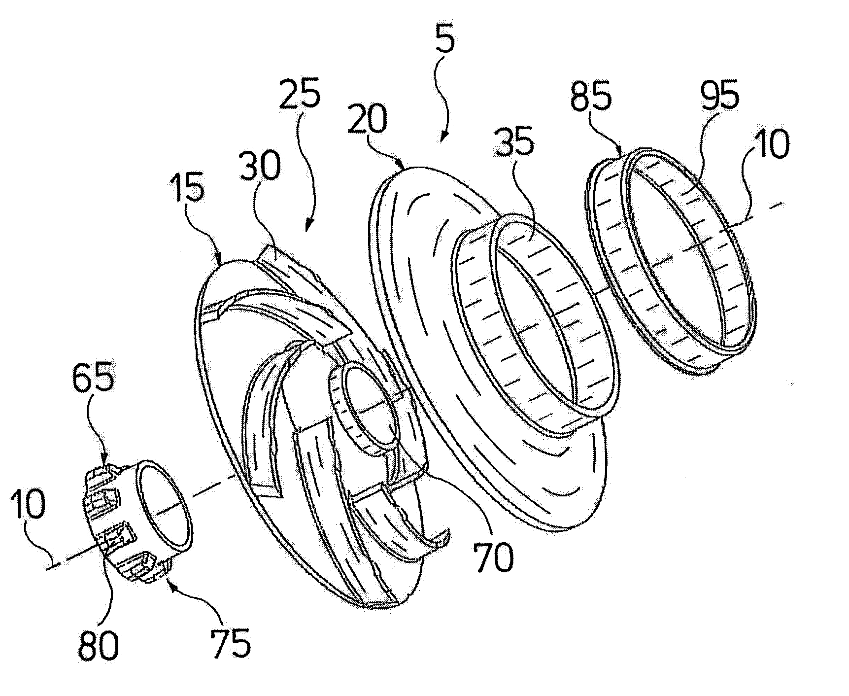
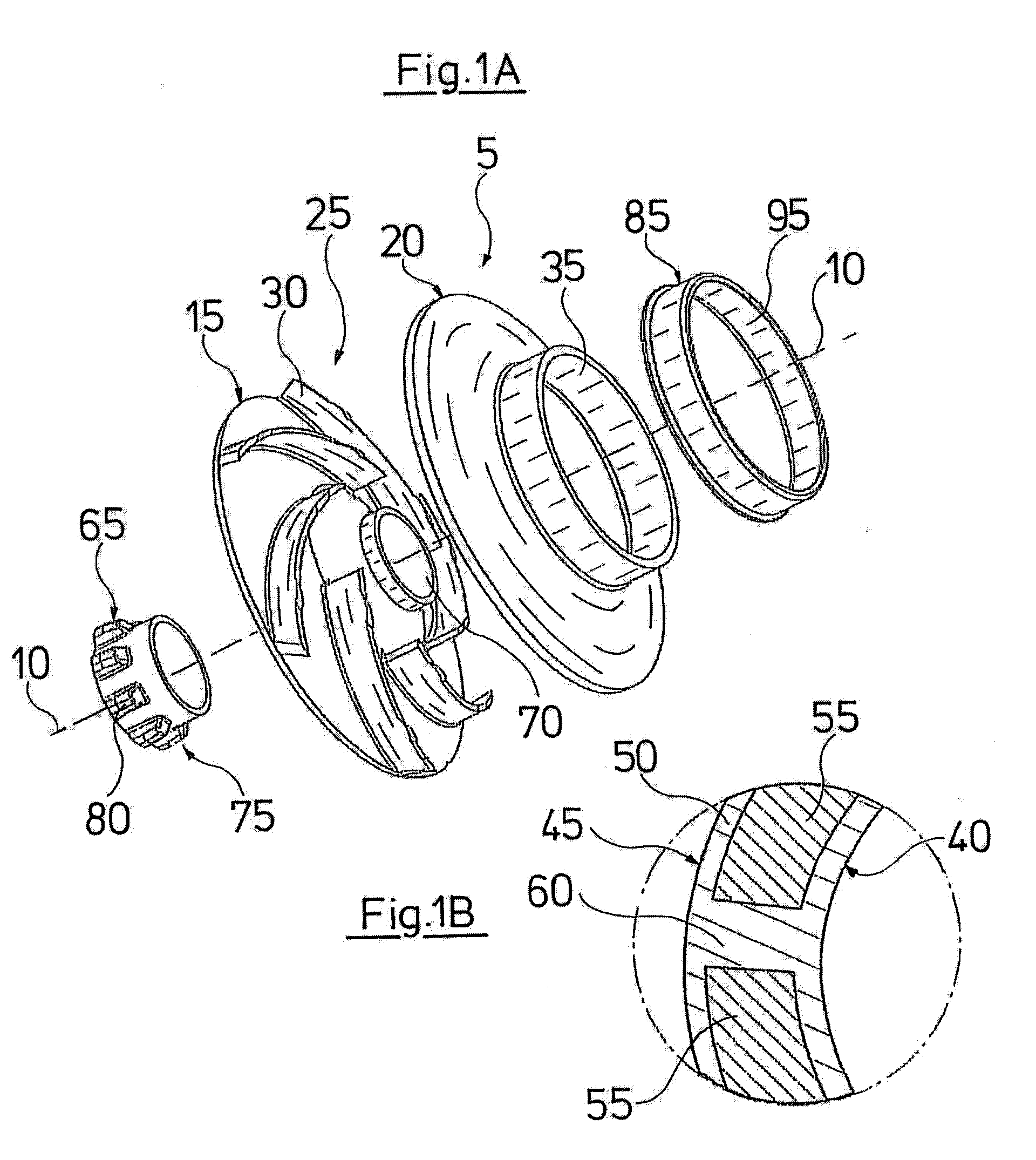
[0031]A flow-leading part of the pump is a component of an impeller 5 constructed of several parts. The construction of this impeller 5 is represented in FIG. 1A. The individual components of the impeller 5 thereby are all arranged coaxially to the rotati...


PUM


Abstract

A pump, in particular a centrifugal pump, includes at least one flow-leading part with an at least regional surface layer (50) of an elastomer. The flow-leading part with the surface layer (50) is formed as a multi-component injection moulded part, with a base structure (55) made of plastic as a first component, and with the elastomer as a second component.

Description

BACKGROUND OF THE INVENTION[0001]The invention relates to a pump and, in particular, to a centrifugal pump. The life duration of pumps, amongst other things, depends on the nature of the fluid to be delivered. For example, foreign matter in the fluid, such as sand-like particles, leads to a wearing of parts of the pump.BRIEF SUMMARY OF THE INVENTION[0002]It is therefore an object of the present invention to provide a pump, which may also be operated in a reliable manner with foreign matter in the fluid to be delivered and which has a high durability. This objective is achieved by a pump with the features specified in the independent claim. Advantageous designs are specified in the dependent claims, the subsequent description and the drawings.[0003]With regard to the pump according to the invention, it is preferably a centrifugal pump. The pump comprises at least one part leading the flow, with a surface layer of an elastomer, which is deposited at least in regions. This flow-leading...

Claims


Application Information

Patent Timeline
IPC IPC(8): F04D29/08F04D29/44F04D29/28
CPCF04D7/04F04D29/026F04D29/086F04D29/2227F05C2225/00F04D29/4286F04D29/448F05B2230/30F05B2230/90F04D29/2294F05D2300/43F05D2230/20F05D2230/53
Inventor VEDSTED, PER FROSTERIKSEN, OLUF
Owner GRUNDFOS MANAGEMENT AS
Why Eureka
Try Eureka