Flow-Routing Component of a Pump
- Summary
- Abstract
- Description
- Claims
- Application Information
AI Technical Summary
Benefits of technology
Problems solved by technology
Method used
Image

Examples
Embodiment Construction
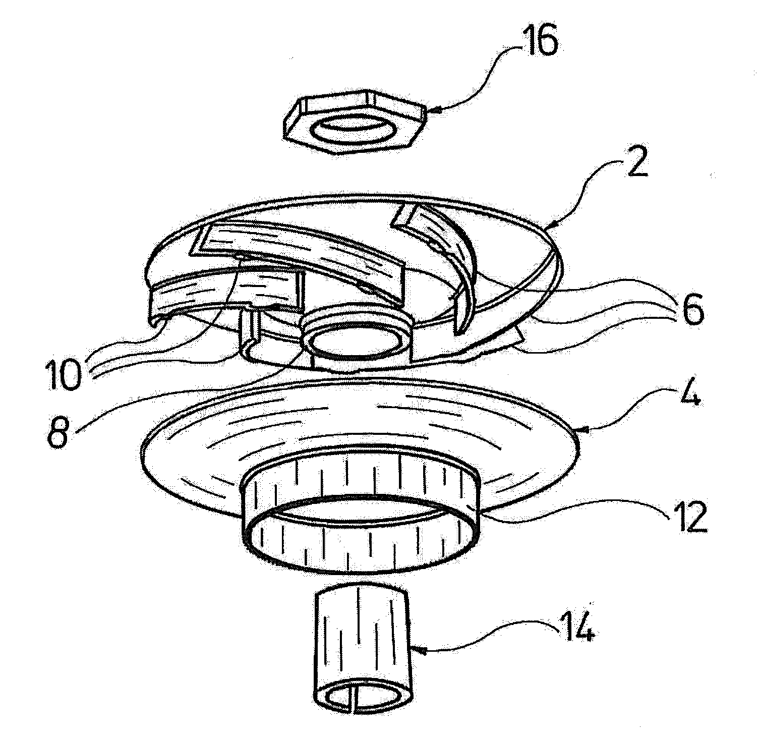
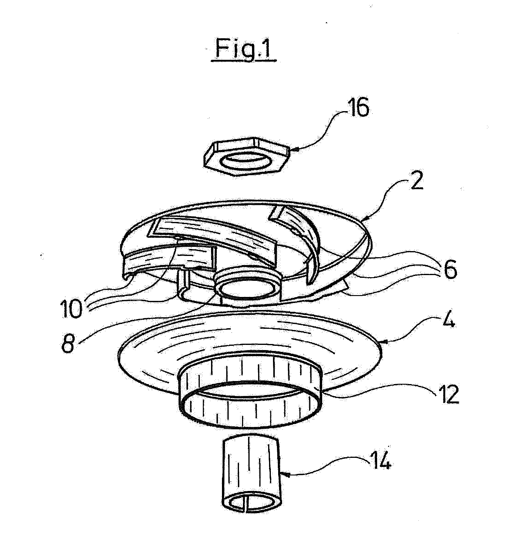
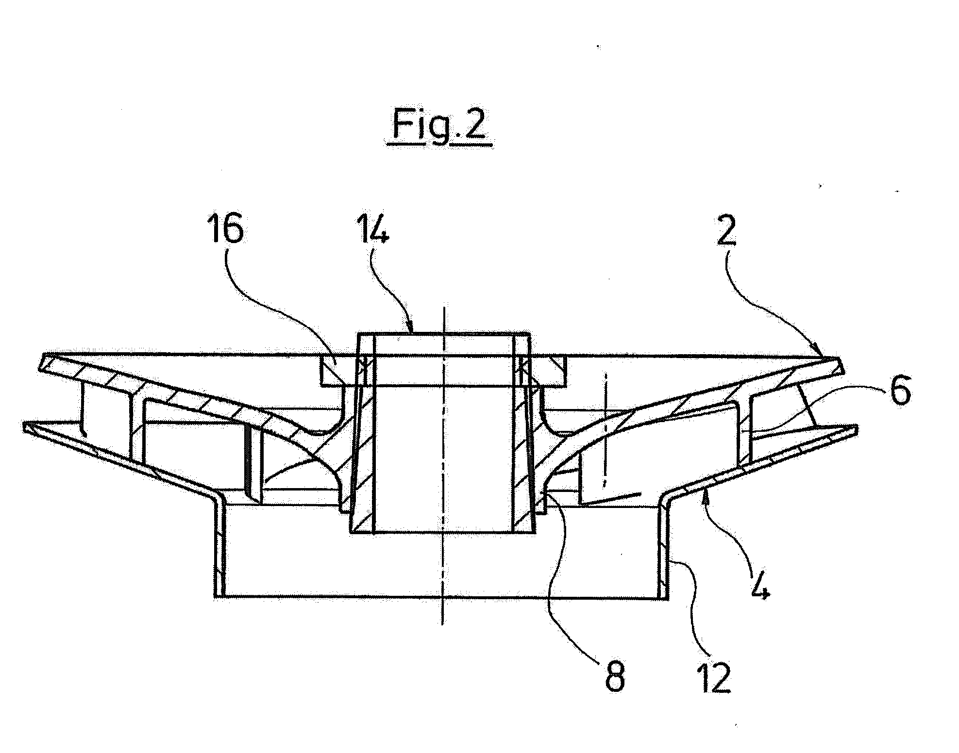
[0032]A flow-routing component according to one embodiment of the invention, which is configured as a pump impeller of a centrifugal pump assembly, is described in more detail with reference to FIGS. 1 and 2.
[0033]The impeller consists essentially of two parts, to be precise a first shroud 2 and a second shroud 4. The first shroud 2 carries the blades 6 and has at its center a hub 8 which serves for fastening to a drive shaft. The first shroud 2 forms, together with the blades 6 and the hub 8, a first part of the impeller. This first part is manufactured from metal, for example stainless steel, by metal-powder injection molding. In this case, the shroud 2, blades 6 and hub 8 are manufactured in one piece in one operation. Metal-powder injection molding makes it possible to produce very simply the plurality of blades, together with the shroud 2 and hub 8, in one piece in one operation. By metal-powder injection molding, even complex blade geometries of the blades 6 can be produced ve...
PUM
| Property | Measurement | Unit |
|---|---|---|
| Fraction | aaaaa | aaaaa |
| Fraction | aaaaa | aaaaa |
| Fraction | aaaaa | aaaaa |
Abstract
Description
Claims
Application Information