
Nanofluid Production Apparatus and Method

a production apparatus and a technology of nanofluid, applied in the direction of cleaning the installation of drawing off water, cleaning using liquids, separation processes, etc., can solve the problems of large size, difficult to use and perform matching, and difficult to put nanofluid to practical use, etc., to reduce the manufacturing cost of nanofluid, simple and inexpensive structure, and easy and fast intra-apparatus cleaning

Inactive Publication Date: 2010-01-14
WATANABE SADATOSHI
View PDF7 Cites 21 Cited by
  • Summary
  • Abstract
  • Description
  • Claims
  • Application Information

AI Technical Summary

Benefits of technology

[0021]In order to address the above challenges, the objective of the present invention is to provide an apparatus and a method for generating nanofluid, which apparatus has a relatively simple and inexpensive structure, is easy to use, and capable of generating a large amount of nanofluid continuously and stably, and substantially reducing the manufacturing cost by efficient cleaning.
[0025]In this manner, any internal areas in contact with the gas-liquid mixture fluid during the nanofluid generation mode may be thoroughly cleaned, and the nanofluid generation and cleaning modes may be instantaneously switched to each other, allowing to minimize the time for preparing for the cleaning and time for returning to the generation mode to thereby improve overall manufacturing efficiency. This further enables to reduce a nanofluid manufacturing cost.
[0026]Also by utilizing the nanofluid generating apparatus provided with the above structure, there may be provided a beverage generation apparatus with a simple structure capable of stably producing a beverage containing nanobubbles. Beverages containing nanobubbles offer unique sensation and taste by acting on cells in the human tongue surface (taste buds, or caliculus gustatorius) and throat internal wall, and retain their quality with nanobubbles freely floating inside the fluid over several months to reduce the change in quality over time (e.g., degassing in beer and carbonated beverages). Freely floating in the beverages for a long period of time, nanobubbles provide a secondary effect to, for example, facilitate wine maturation.
[0027]Moreover, by utilizing the nanofluid generating apparatus provided with the above structure, there may be provided a therapeutic fluid generating apparatus with a simple structure capable of stably producing therapeutic fluid (a drug) containing nanobubbles. Liquid-type drugs containing fine nanobubbles are capable of entering gaps in, and acting directly on cells and the like, and are expected to provide efficacy with a small dosage. Also for patients with various allergic dermatosis including atopic dermatitis, treatment or cleaning with anti-irritant drugs or purified water may be provided to reduce loads on patients such as side effects and facilitate their treatment.
[0028]When an ozonizer is provided as a cleaning fluid generating means, ozone generated by the ozonizer may clean the inside of the nanofluid generating apparatus during the cleaning mode, and ozone-containing nanofluid may be generated during the nanofluid generation mode. Such nanofluid containing nano-sale ozone may offer, for example, a superior sterilization effect for an extended period. On the other hand, an ozone filter is preferably installed around the nanofluid generating apparatus or in the vicinity of the nano-outlet to collect ozone present in an excess amount or ozone used for cleaning due to known direct effects of a large quantity of ozone on human health, such as causing eye pain, headache and breathing disorder. In addition, different amounts of ozone are preferably generated during the nanofluid generation mode and during the cleaning mode.
[0031]According to the present invention, a large amount of nanofluid may be generated continuously and stably with a relatively simple, inexpensive and easy-to-use structure, providing an effect to substantially reduce the nanofluid manufacturing cost. In addition, the nanofluid generating apparatus of the present invention allows to ensure easy and fast intra-apparatus cleaning, capable of providing nanofluid even in the applications requiring a high level of hygiene, and improving the overall efficiency of nanofluid production including the cleaning process to thereby reduce the nanofluid manufacturing cost.

Problems solved by technology

It has been verified that the nanobubbles described above are generated instantaneously when microbubbles collapse in the water, and are known for their extremely unstable physical characteristics.
Therefore it is difficult to put nanobubbles to practical use by stably producing and retaining them for an extended period of time.
However, ultrasonic generators are expensive, large-sized and difficult to use and perform matching, prohibiting their wide use.
However, this apparatus only generates microbubbles, and does not stably produce nanobubbles with smaller diameter.
Similarly, applying the technology disclosed in the Patent Document 6 does not achieve stable and low-cost generation of nanofluid containing nanoscale bubbles.
Such cleaning work is generally carried out by immersing each disassembled part of the apparatus separately from other parts in a cleaning solution, or applying the cleaning solution to the parts, during which work the nanofluid production needs to be deactivated, resulting in higher manufacturing costs.

Method used


Image

  • Nanofluid Production Apparatus and Method
  • Nanofluid Production Apparatus and Method
  • Nanofluid Production Apparatus and Method

Examples


Embodiment Construction

[0035]Embodiments of the present invention will be described below based on the accompanying drawings.

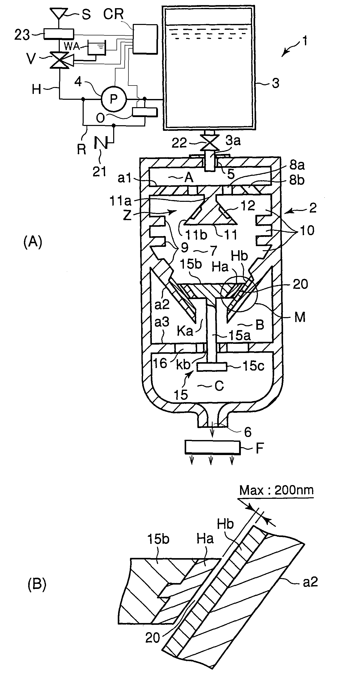
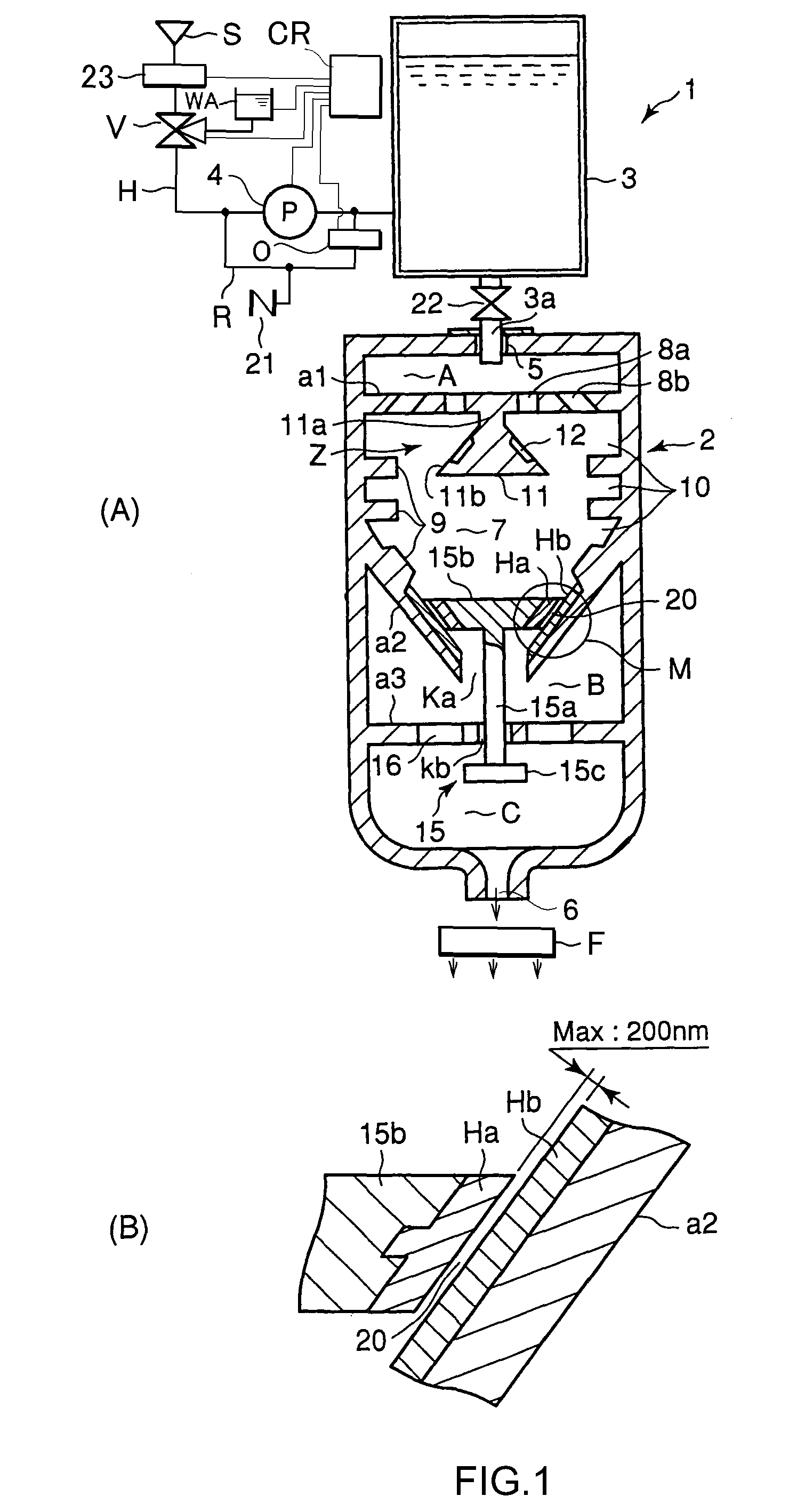
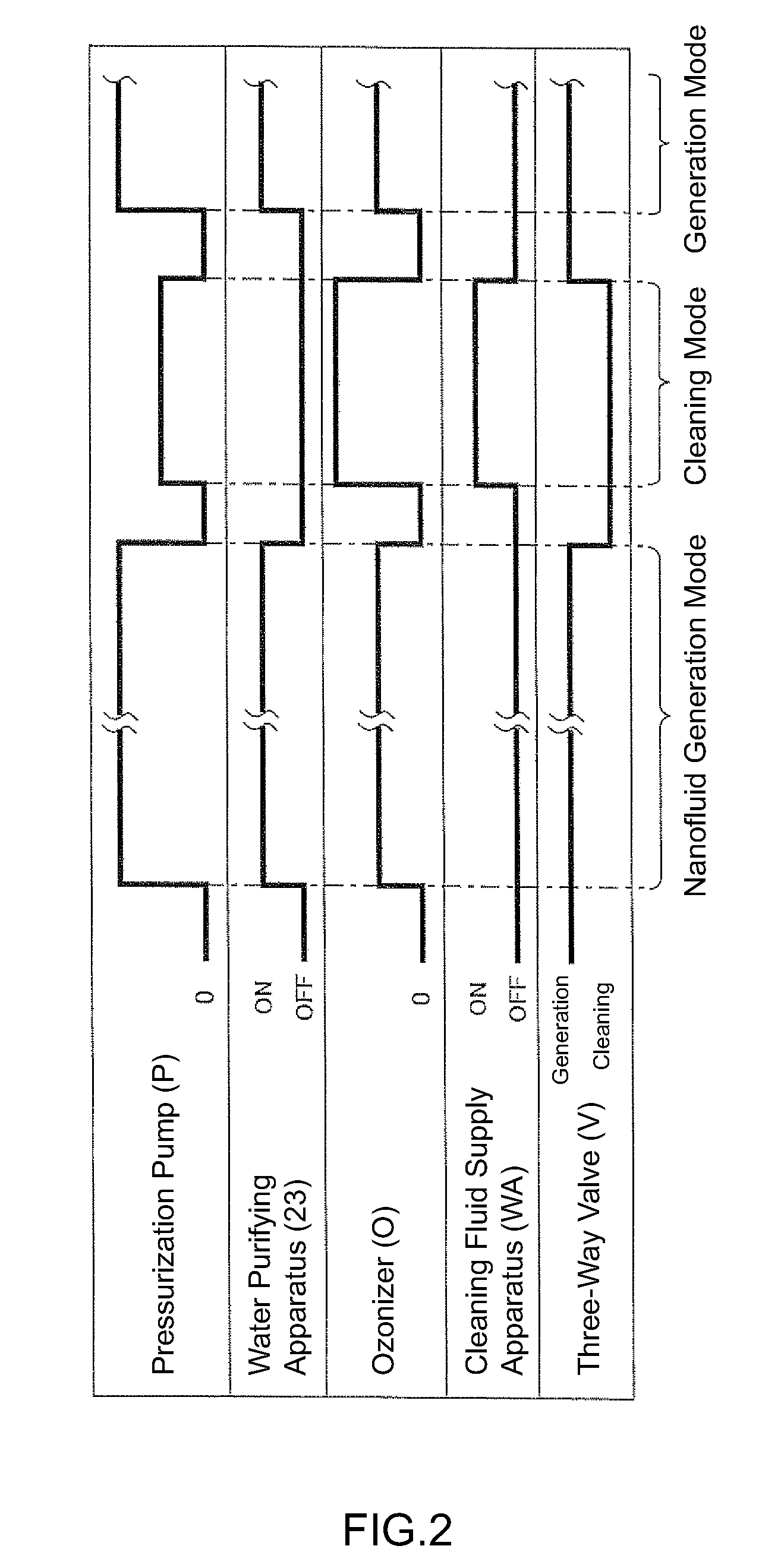
[0036]FIG. 1(A) is a schematic cross-sectional view of a nanofluid generating apparatus 1 according to one embodiment of the present invention; FIG. 1(B) is a fragmentary sectional view showing an enlarged key portion M, which is circled in FIG. 1(A); and FIG. 2 is a timing diagram showing a control flow by a control unit.

[0037]The nanofluid generating apparatus 1 is composed of a generator 2, a holding tank 3, a pressurization pump (pressurization means) 4, a piping H in communication with the generator 2 from a water supply source through the pressurization pump 4 and the holding tank 3, an ozonizer O for generating ozone, a control unit (control section) CR for switching and controlling a nanofluid generation mode and an intra-apparatus cleaning mode, a ozone filter F for collecting ozone, and a cleaning unit WS for cleaning the inside of the apparatus.

[0038]A water purifying app...


PUM

PropertyMeasurementUnit
diameteraaaaaaaaaa
widthaaaaaaaaaa
diameteraaaaaaaaaa

Abstract

The object of the invention is to provide an apparatus and a method for generating a large amount of nanofluid continuously and stably with a relatively simple, inexpensive and easy-to-use structure, and for efficiently performing an intra-apparatus cleaning operation to substantially reduce the nanofluid manufacturing cost.A nanofluid generating apparatus 1 for generating nanofluid containing nanobubbles, wherein the nanobubbles are gas bubbles with diameter less than 1 μm, comprises a gas-liquid mixing chamber 7, comprising a turbulence generating mechanism for forcibly mixing supplied gas and liquid by generating turbulence, and a nano-outlet 20 for discharging the gas-liquid mixture fluid to outside of the gas-liquid mixing chamber to generate nanofluid; a gas-liquid supply apparatus 21, 23, . . . for supplying gas and liquid to the gas-liquid mixing chamber 7; a pressurization pump for applying pressure to the gas and liquid; and a control unit CR for controlling operations of the pressurization pump 4 and the gas-liquid supply apparatus. The control unit CR controls the gas-liquid supply apparatus and the pressurization pump 4 to switch between a nanofluid generation mode and a cleaning mode for cleaning the inside of the gas-liquid mixing chamber 7.

Description

CROSS REFERENCE TO RELATED APPLICATIONS[0001]This application claims priority under 35 U.S.C. 119 based upon U.S. Provisional Application No. 60 / 719,937, filed on Sep. 23, 2005 and the International Patent Application No. PCT / JP2006 / 301736, filed on Feb. 2, 2006. The entire disclosure of which is incorporated herein by reference.THE FIELD OF THE INVENTION[0002]The present invention relates to an apparatus and a method for generating nanofluid containing nanobubbles, which are gas bubbles with diameter less than 1 μm; an apparatus and a method for generating beverages containing nanofluid; an apparatus and a method for treating dermatosis using nanofluid; and an apparatus and a method for assisting the growth of organisms using nanofluid.BACKGROUND OF THE INVENTION[0003]In general, submicroscopic gas bubbles with diameter less than 1 μm (1000 nm) are called “nanobubbles,” whereas microscopic gas bubbles with diameter equal to or greater than 1 μm are called “microbubbles.” The nanobu...

Claims


Application Information

Patent Timeline
Patent Type & Authority Applications(United States)
IPC IPC(8): A61M37/00B01F3/04B01J19/08B08B9/02B01F25/70
CPCB01F3/0446B01F5/0268B08B3/048B01F2003/04858B08B3/10B01F5/0665Y10T137/0402B01F23/232B01F25/25B01F25/4413B01F23/2375
Inventor WATANABE, SADATOSHI
Owner WATANABE SADATOSHI
Learn More