System and method for controlling a heart stimulator

a heart stimulator and system technology, applied in the field of implantable heart stimulators, can solve the problems of weakened or absent hrt response, patients whose hrt is absent or weakened suffer a higher and achieve the effect of reducing the risk of sudden cardiac death

a heart stimulator and system technology, applied in the field of implantable heart stimulators, can solve the problems of weakened or absent hrt response, patients whose hrt is absent or weakened suffer a higher and achieve the effect of reducing the risk of sudden cardiac death

US20100010555A1Active Publication Date: 2010-01-14ST JUDE MEDICAL

Image

  • System and method for controlling a heart stimulator
  • System and method for controlling a heart stimulator
  • System and method for controlling a heart stimulator

Examples


Embodiment Construction

[0046]The following is a description of exemplifying embodiments. This description is not to be taken in a limiting sense, but is made merely for the purpose of describing general principles of the invention. Thus, even though particular types of heart stimulators will be described, the invention is also applicable to any other types of cardiac stimulators having pacing and vagal stimulation capabilities.

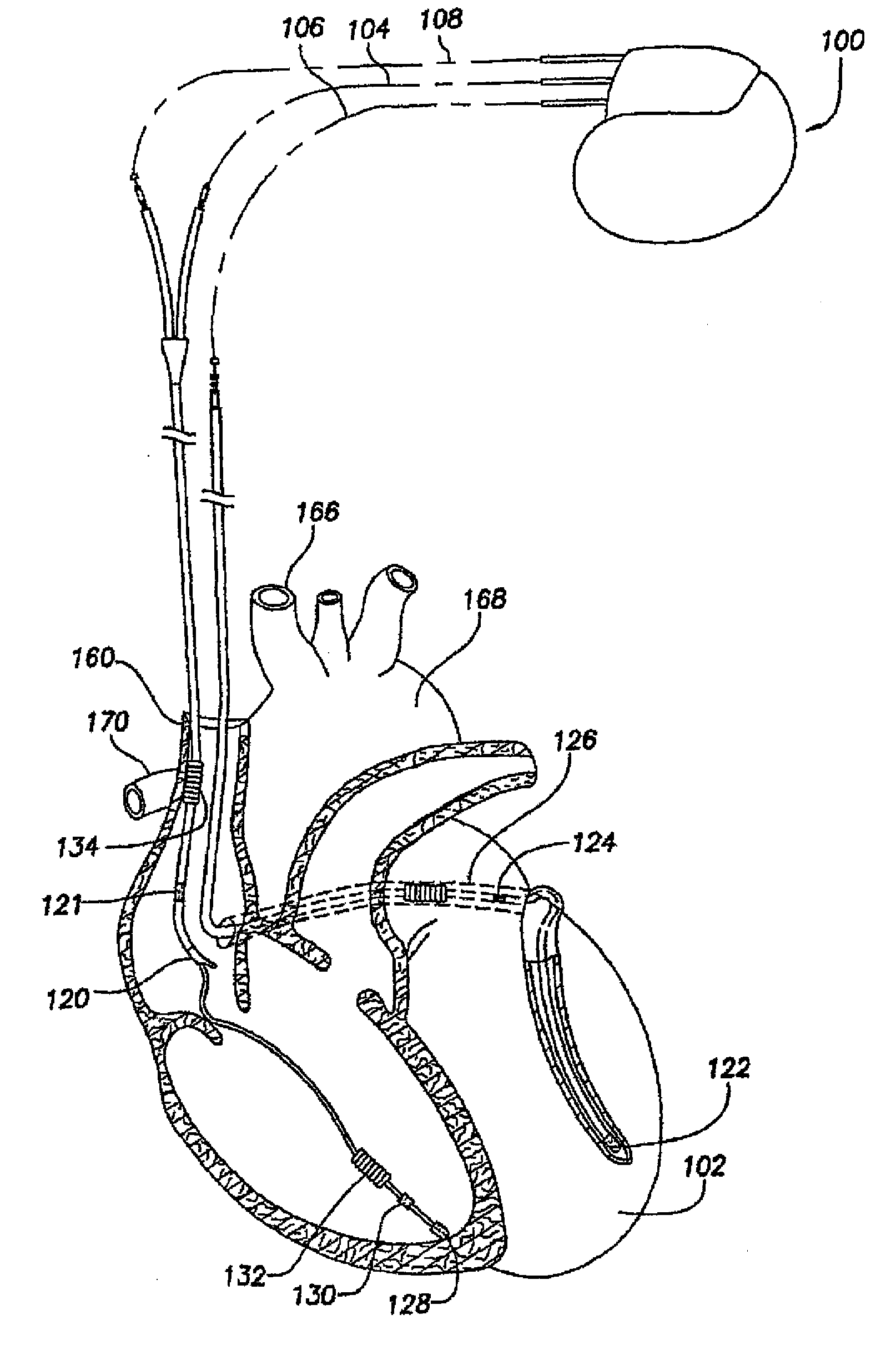
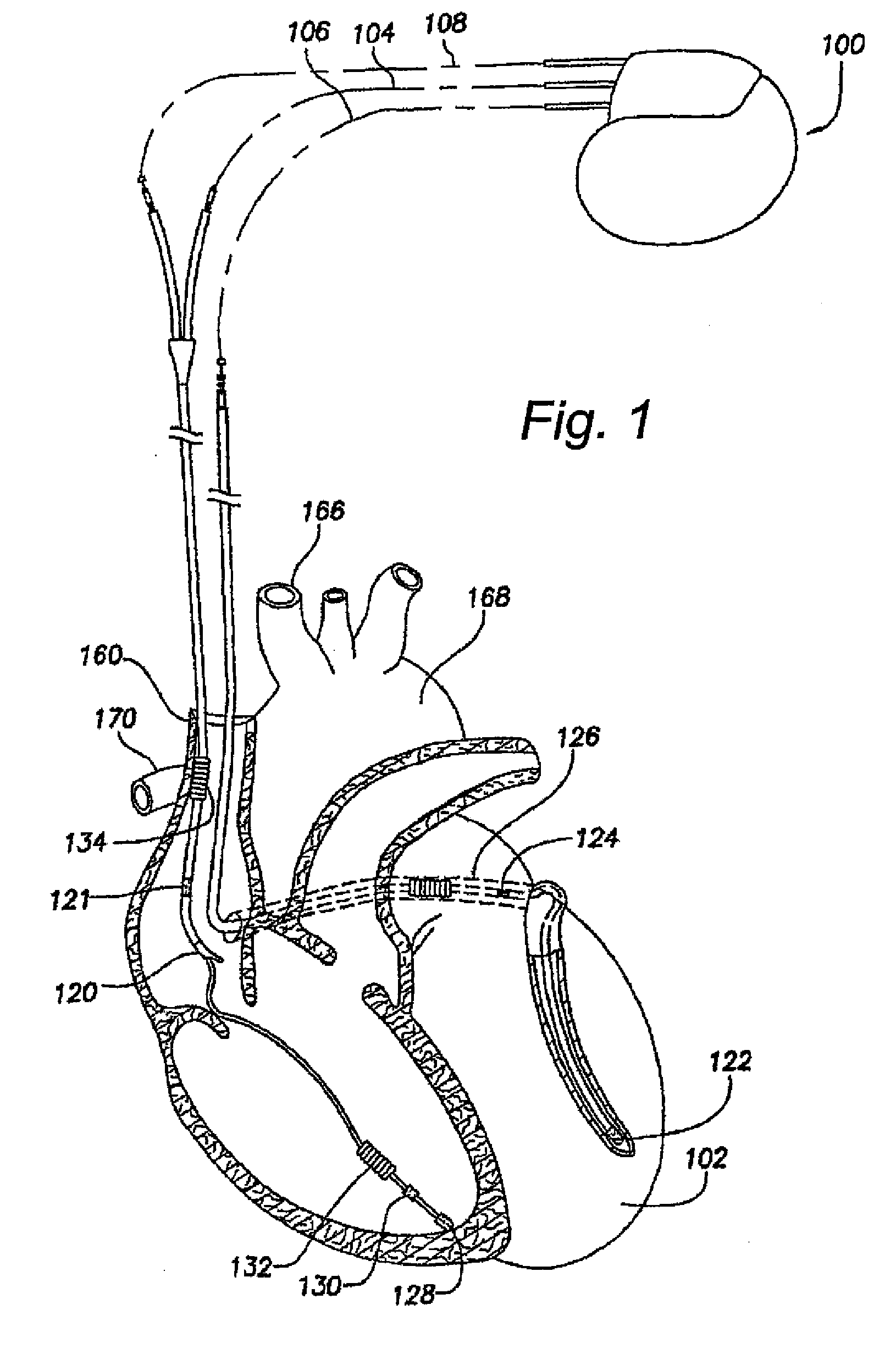
[0047]With reference first to FIG. 1, there will now be described an exemplary prior art stimulation device 100 for which the following exemplifying embodiments are applicable. The stimulation device 100 is in electrical communication with a patient's heart 102 by way of three electrical “connections”104, 106, and 108, suitable for delivering multi-chamber stimulation and shock therapy. While two of the electrical connections (104 and 108) are shown as a single-pass lead, it is to be understood that individual leads could also be used to describe the fundamentals of multi-chamber st...


PUM


Abstract

In a system and method for controlling an implantable stimulator capable of producing pacing pulses to be delivered to cardiac tissue, as well as vagal stimulation pulses to be delivered to vagus nerve sites, upon detection of a premature cardiac event, such as a premature ventricular or atrial contraction, a simulated heart rate turbulence (HRT) procedure is applied if the intrinsic heart rate turbulence is weakened or absent. The simulated HRT includes a first phase in which the heart rate is increased, from the existing level, for a number of heart beats, a second phase in which the heart rate is decreased for a number of heart beats, and an optional third phase in which the heart rate is returned to said existing level.

Description

TECHNICAL FIELD[0001]The present invention generally relates to the field of implantable heart stimulation devices, such as pace-makers, implantable cardioverter-defibrillators (ICD), and similar cardiac stimulation devices. More specifically, the present invention relates to a system for controlling an implantable heart stimulator, an implantable heart stimulator including such a system, a method for operating an implantable heart stimulator, a computer program product and a computer readable medium.BACKGROUND ART[0002]Heart Rate Turbulence (HRT) is a dual-phased physiological response of the sinus node to a premature ventricular event or contraction (PVC), for instance a ventricular extra systole (VES), which in turn is an intrinsic ventricular contraction occurring early in relation to when the next regular ventricular contraction is expected. The first or initial phase of the HRT consists of a short acceleration of the heart rate, and the second or subsequent phase consists of a...

Claims


Application Information

Patent Timeline
14 Jan 2010
Publication
US20100010555A1
IPC
A61N1/365
CPC
A61B5/02405; A61B5/4035; A61N1/365; A61N1/3622; A61N1/36114
Inventors
NOREN, KJELL; FARAZI, TARANEH G.