Water feature for wave pools

Active Publication Date: 2010-01-21
JOHNSON GARRETT TYLER
View PDF26 Cites 12 Cited by
  • Summary
  • Abstract
  • Description
  • Claims
  • Application Information

AI Technical Summary

Benefits of technology

[0011]The present invention is directed to providing a means of reducing backflow caused by the breaking of high volume, generated wave

Problems solved by technology

Because of the nature of compressed gas, wave cannons may transfer large amounts of energy while providing unobtrusive infrastructure.
In contrast, conventional wave generating technologies have been somewhat limited in the energy that can be imparted to the pool, based on the practical limits of size, mechanics, infrastructure, and cost.
Thus, most wave pools are limited in size, with the larger wave pools being in the form of oversized swimming pools.
A problem present in all conventional wave pools is the backwash caused by breaking waves.
However, the back

Method used


Image

  • Water feature for wave pools
  • Water feature for wave pools
  • Water feature for wave pools

Examples


Embodiment Construction

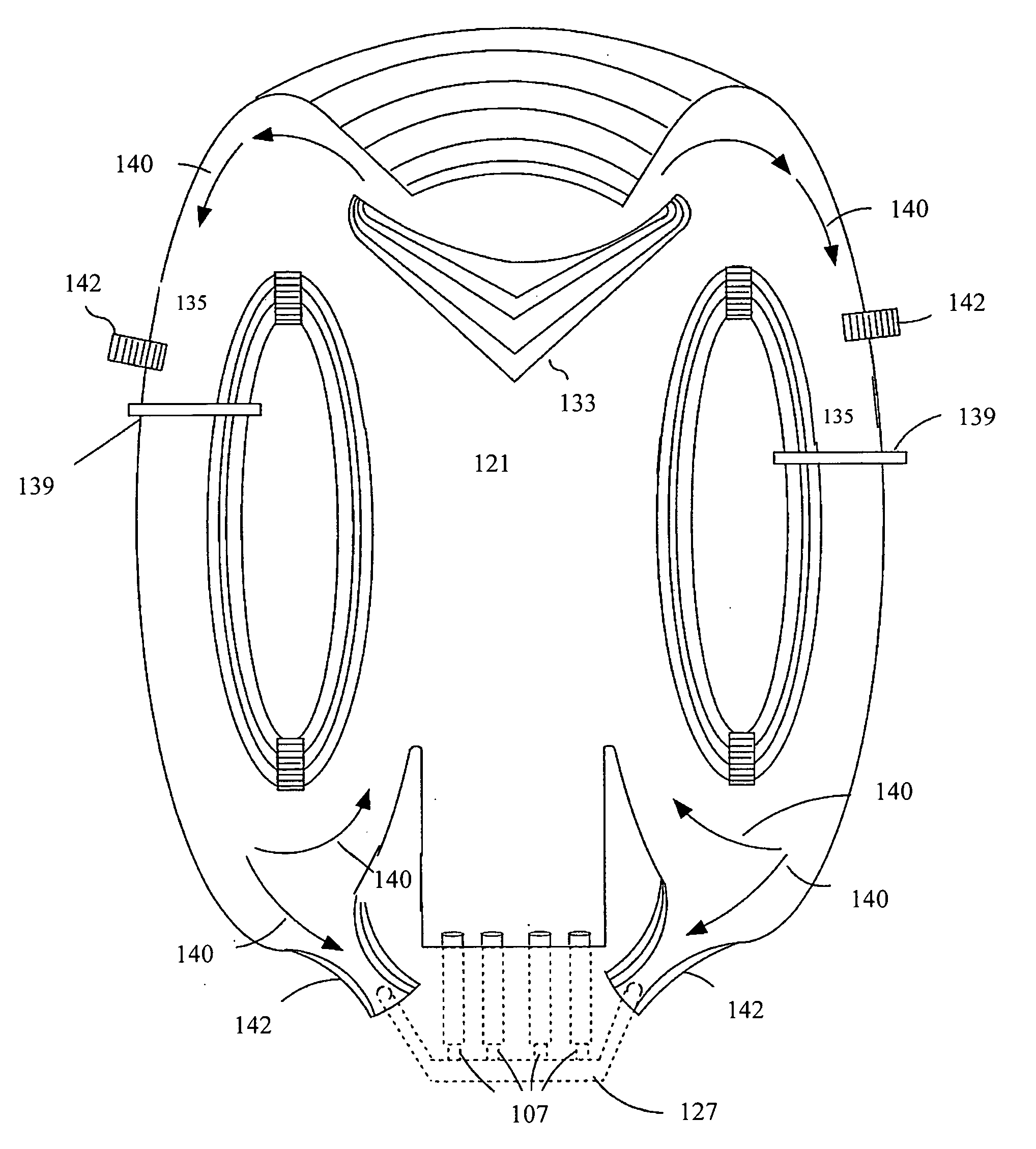
[0025]As introduced above, the present invention provides a means of reducing backflow caused by the breaking of high volume, generated waves within a wave pool, while also providing strong circulating currents and waves supporting action river activities for swimmers and surfers.

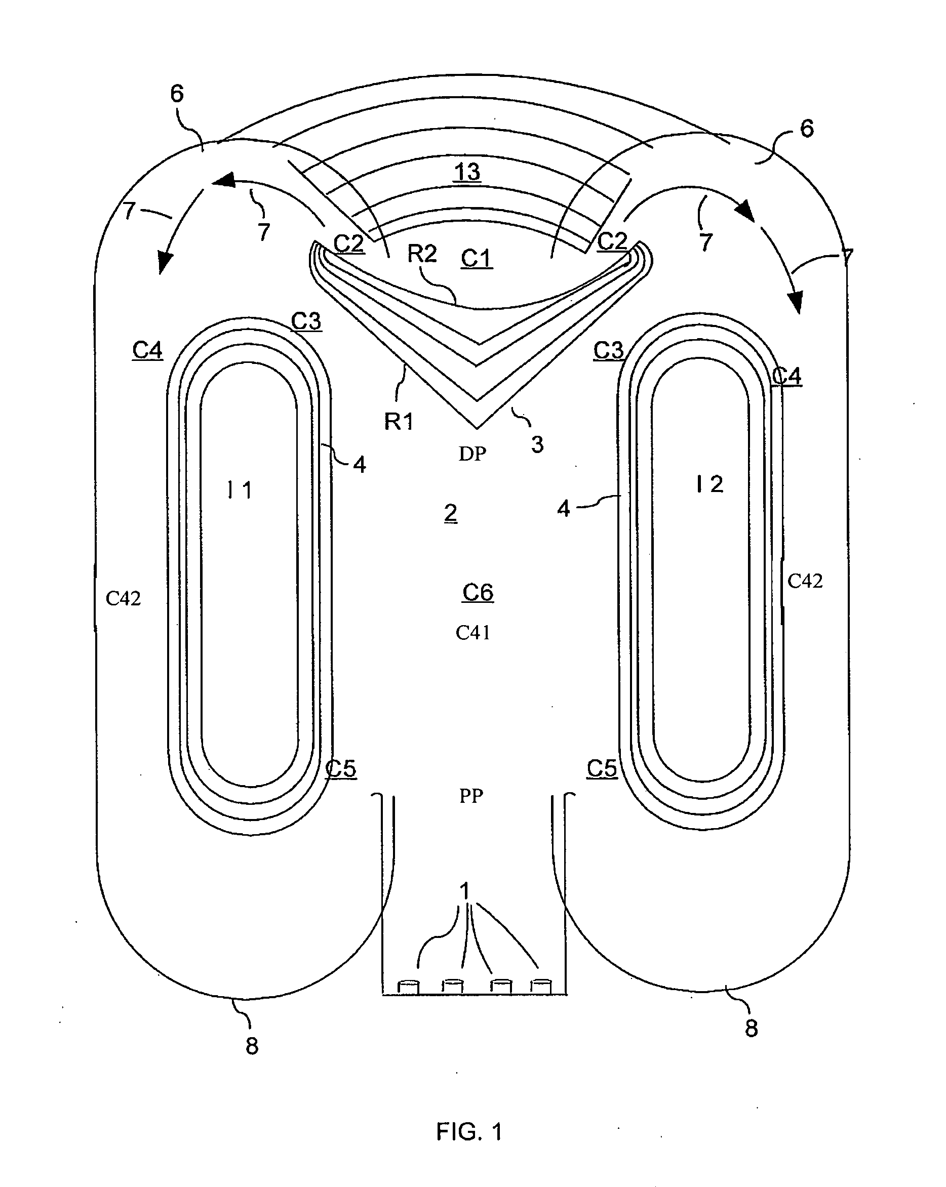
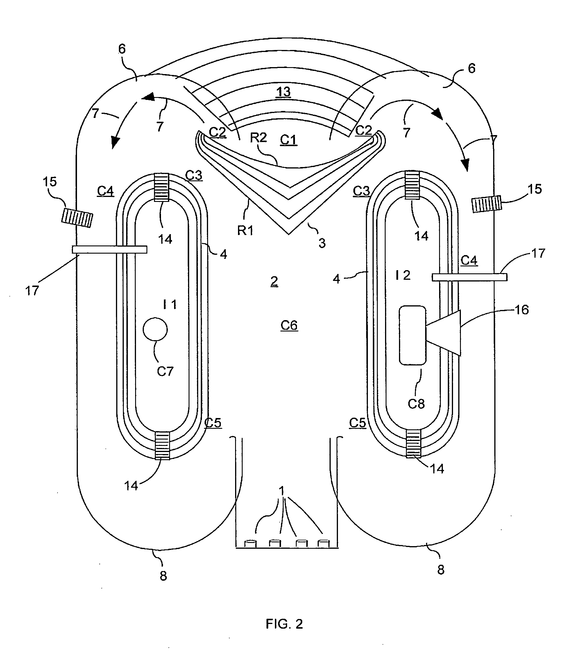
[0026]With reference to the drawings, a top view of an embodiment of the present invention may be seen in FIG. 1. Wave pool 2 has a bottom at desired depths and at least one vertical sidewall 8 adapted to contain the body of water, the body thus having a proximal portion PP and a distal portion DP. Wave pool 2 is adapted to contain a body of water. Wave generator 1 is connected to or disposed in wave pool 2 at a proximal portion PP of the body of water. The bottom and at least one vertical sidewall 8 form a substantially dissipative beach 13 (shown by isobaths) disposed at the distal portion DP of the body of water.

[0027]Optional reef contour 3 (also shown by isobaths) may be disposed at the distal portion ...


PUM


Abstract

The present invention relates to wave pools and diversion channels that capture high kinetic energy portions of a wave generated within the wave pool, and redirects the captured wave portions to the vicinity of wave formation, preferably timed so as reinforce a subsequently generated wave. The high kinetic energy within the diversion channel creates an additional feature in the form of an action river for riders of a wave pool to enjoy. At the same time, capturing of portions of the wave reduces the backwash of the wave and stabilizes the level of water within the wave pool, especially for embodiments with wave generators and pools capable of high volume waves. Riders may enter the diversion channel and ride from the distal, beach end of the wave pool to the proximal, wave generating end.

Description

CROSS REFERENCE TO RELATED APPLICATIONS[0001]This application is a continuation-in-part of U.S. patent application Ser. 11 / 433,035, filed May 12, 2006, which claimed the benefit of priority from U.S. Provisional Application Ser. No. 60 / 680,365, filed May 12, 2005, both of which are hereby incorporated by reference in their entireties. This application is also a continuation-in-part of U.S. patent application Ser. No. 12 / 286,632, filed Oct. 1, 2008, which is (i) a continuation-in-part of U.S. application Ser. No. 11 / 786,652, filed Apr. 12, 2007, which claimed the benefit of priority from U.S. Provisional App. 60 / 878,784, filed Jan. 6, 2007, and U.S. Provisional Application 60 / 789,000, filed Apr. 4, 2006, and (ii) a continuation-in-part of U.S. patent application Ser. No. 11 / 732,233, filed Apr. 3, 2007, now issued as U.S. Pat. No. 7,438,080, which claimed the benefit of priority from U.S. Provisional App. 60 / 789,000 filed Apr. 4, 2006, all of which are hereby incorporated by reference...

Claims


Application Information

Patent Timeline
IPC IPC(8): A47K3/10
CPCE04H4/0006
Inventor JOHNSON, GARRETT TYLER
Owner JOHNSON GARRETT TYLER
Why Eureka
Try Eureka