Thermatically operated bypass valve for passive warmup control of aftertreatment device

a bypass valve and aftertreatment device technology, applied in the direction of valve operating means/release devices, functional valve types, machines/engines, etc., can solve the problems of deteriorating fuel efficiency, different, and complex diesel engine emissions, and achieve the effect of reducing the time of catalyst light o

Inactive Publication Date: 2010-01-21
BORGWARNER INC
View PDF22 Cites 33 Cited by
  • Summary
  • Abstract
  • Description
  • Claims
  • Application Information

AI Technical Summary

Benefits of technology

[0043]At engine start-up, in order to minimize catalyst light off time, it is important that the greatest amount of heat energy possible gets to the catalyst. The present invention accomplishes this by providing a passive, thermatically operated valve, which opens a turbine bypass to re-route the heated exhaust gas flow around the turbine housing, rather than through the turbine housing, which housing would absorb the thermal energy. In this manner more of the thermal energy is delivered to the catalyst. By operating passively, there is no need for expensive and complicated electronic, or electric, controls to command the bypass valve to open and close.

Problems solved by technology

One situation faced by engine manufacturers is that the production of NOx and PM are usually opposed to each other.
However, when engine combustion temperatures are lower, less NOx and more PMs are produced so the engine manufacturers have to trade off these protocols.
The emissions of diesel engines are much more complex than those of gasoline engines so the catalytic solutions are more complex, and definitely different.
For NOx reduction in diesels, while EGR is used today in many cases, it does not satisfy the end user as fuel efficiency deteriorates.
They are all complex, space invasive, and expensive.
These devices are not intended to aid in faster catalyst light off.
The low thermal inertia feature of this design is favorable in reducing the catalyst light off period but the feature helping reduce the catalyst light off period is always present, not passively controlled.

Method used


Image

  • Thermatically operated bypass valve for passive warmup control of aftertreatment device
  • Thermatically operated bypass valve for passive warmup control of aftertreatment device
  • Thermatically operated bypass valve for passive warmup control of aftertreatment device

Examples


Embodiment Construction

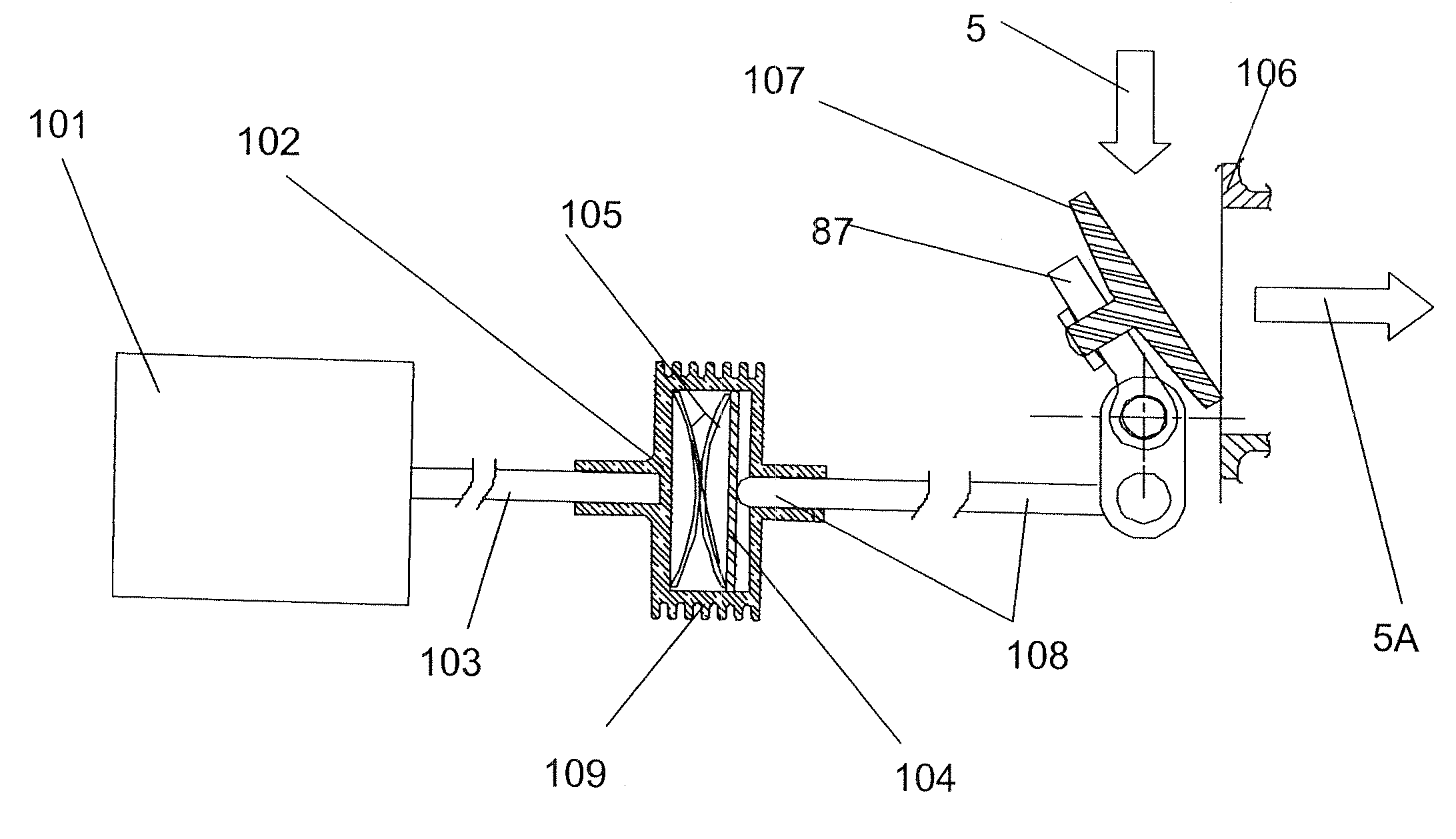
[0061]On a turbocharged internal combustion engine the turbine housing includes a valve and a port, on the upstream side of the turbine wheel. The valve and port are fluidly coupled to the gas flow upstream of the turbine wheel. Said valve and port are in the closed, sealed, position while the engine is running at normal operating temperature, directing all the exhaust gas flow through the turbine wheel. The exhaust gas pressure provides pressure on the valve, to help in sealing, during normal engine operating conditions. However, at start up, when the engine is cold, the passive, bi-metallic valve distorts thermatically to an open position, thus allowing the pressure generated by the stationary, or slowly rotating, turbine wheel, to bias the exhaust flow through the valve and port to the low thermal inertia bypass system and thus pre-heat the after-treatment device(s), This has the effect of shortening the light-off period for the catalyst.

[0062]This valve is most preferably a bi-m...


PUM


Abstract

In order for automobile exhaust catalysts to function they must be at operational temperatures. When an engine starts from cold the vehicle, including the exhaust system and any after-treatment device located therein, is at ambient temperature. Since 60% to 80% of the total emissions emitted occur at engine cold start and idle up to 120 seconds, it is imperative that the catalyst function as fast as possible. This invention provides a passive thermatically controlled bypass valve to enable the exhaust flow to bypass the enthalpy loss incurred by driving the turbine wheel of a turbocharger, and thus more rapidly deliver heat to the catalyst or after-treatment.

Description

FIELD OF THE INVENTION[0001]Wastegate valves, which allow some of the exhaust gas to bypass the turbine wheel, and fluidly connect to the turbine housing downstream of the turbine wheel, are actuated by any of: vacuum, boost pressure and electronics, and are controlled by any of boost pressure, exhaust pressure and vacuum in a manifold, in which cases the control is passive, or: electronics commanded by the ECU of the engine or vehicle, in which case the control is active. The invention provides a new type of wastegate valve control and acuation.DESCRIPTION OF THE RELATED ART[0002]Turbochargers consist of five major groups of parts: a bearing housing (30) supporting a turbine wheel (31) and a turbine housing (39) on the hot side, and a compressor wheel (33) and a compressor housing (30) on the cold side. The turbine housing (39) is fed exhaust gas (5) from the engine, through an exhaust manifold (43). The turbine housing exhausts gas to a vehicle down-pipe (44) through an exducer (3...

Claims


Application Information

Patent Timeline
IPC IPC(8): F02D23/00F01N3/10
CPCF01D17/085F01D17/141F01N13/08F01N13/1816F05D2220/40F02B37/186F16K31/002Y02T10/144F02B37/183Y10T137/7737Y02T10/12
Inventor ANDREWS, DAVID
Owner BORGWARNER INC
Why Eureka
Try Eureka