Parabolic Trough Solar Reflector With An Independently Supported Collector Tube

a solar reflector and collector tube technology, applied in the direction of solar heat collector controllers, joists, building components, etc., can solve the problems of high cost, high cost, and high cost of electricity generation using existing conventional energy sources such as coal, natural gas and nuclear, and achieve the effect of increasing the operating range and making electricity generation from solar thermal energy more affordabl

Active Publication Date: 2010-03-18
JENNINGS KEVIN
View PDF24 Cites 26 Cited by
  • Summary
  • Abstract
  • Description
  • Claims
  • Application Information

AI Technical Summary

Benefits of technology

[0008]Another object is to provide a parabolic trough solar collector which allows direct steam generation, avoiding the use of a heat transfer fluid.
[0009]These and other objects of the present invention are achieved by providing a simpler and lower cost version of a parabolic trough solar collector system, having a collector tube supported independently from the parabolic trough reflector. The collector tube remains stationary along the focus line relative to the movement of the reflector. Allowing the collector tube to be independently mounted and stationary enables the collector tube to be provided without the numerous flexible and / or rotational joints associated with existing systems. Additionally, removing these joints allows the tube to be made of a stronger material which enables the collector tube to contain fluids for operating at higher pressures and temperatures. Eliminating the flexible joints and allowing for the higher operating ranges of the stronger collector tube enable the present invention to generate superheated steam directly in the collector tube. This eliminates the secondary heat transfer systems associated with existing systems using synthetic oil as a thermal fluid. Consequently, the present invention makes generating electricity from solar thermal energy more affordable than existing parabolic trough systems.

Problems solved by technology

The cost to generate electricity using the existing parabolic trough systems remains much higher than the cost to produce electricity using existing conventional energy sources such as coal, natural gas and nuclear.
These higher costs are partly due to the complexity of the existing parabolic trough support structure.
These expensive structures include the trusses that support the parabolic reflector.
Existing parabolic troughs in operation today are limited in size due to the cost / benefit relationship of structure to the width of the parabolic reflector.
The weight of the collector tube connected to the trough adds to these structural loadings.
These joints limit the operating temperatures and pressures of the collector tube, and provide a source for loss of thermodynamic efficiency, wear and possible leakage.
This heat transfer results in some loss of energy efficiency.
Existing parabolic trough systems using synthetic oil are further limited by the maximum operating temperature of existing synthetic oil which currently is about 400 degrees C. Above 400 degrees C., existing synthetic oil's thermal stability degrades leading to lower heat transfer efficiency and an increased creation of degradation by-products.
The 400 degree C. operating temperature limitation of the synthetic oil also represents the operating temperature limitation of the steam being sent to the turbines for the production of electricity.
The optimum operation temperature for an electrical generating steam turbine is much higher than 400 degrees C. This operating temperature limitation imposed by the synthetic oil further reduces the efficiency of existing systems using synthetic oil.
The combination of the width limitation on the parabolic trough and the operating limitations on the collector tube results in lower overall efficiencies and higher costs for existing parabolic trough solar collector systems.

Method used


Image

  • Parabolic Trough Solar Reflector With An Independently Supported Collector Tube
  • Parabolic Trough Solar Reflector With An Independently Supported Collector Tube
  • Parabolic Trough Solar Reflector With An Independently Supported Collector Tube

Examples


Embodiment Construction

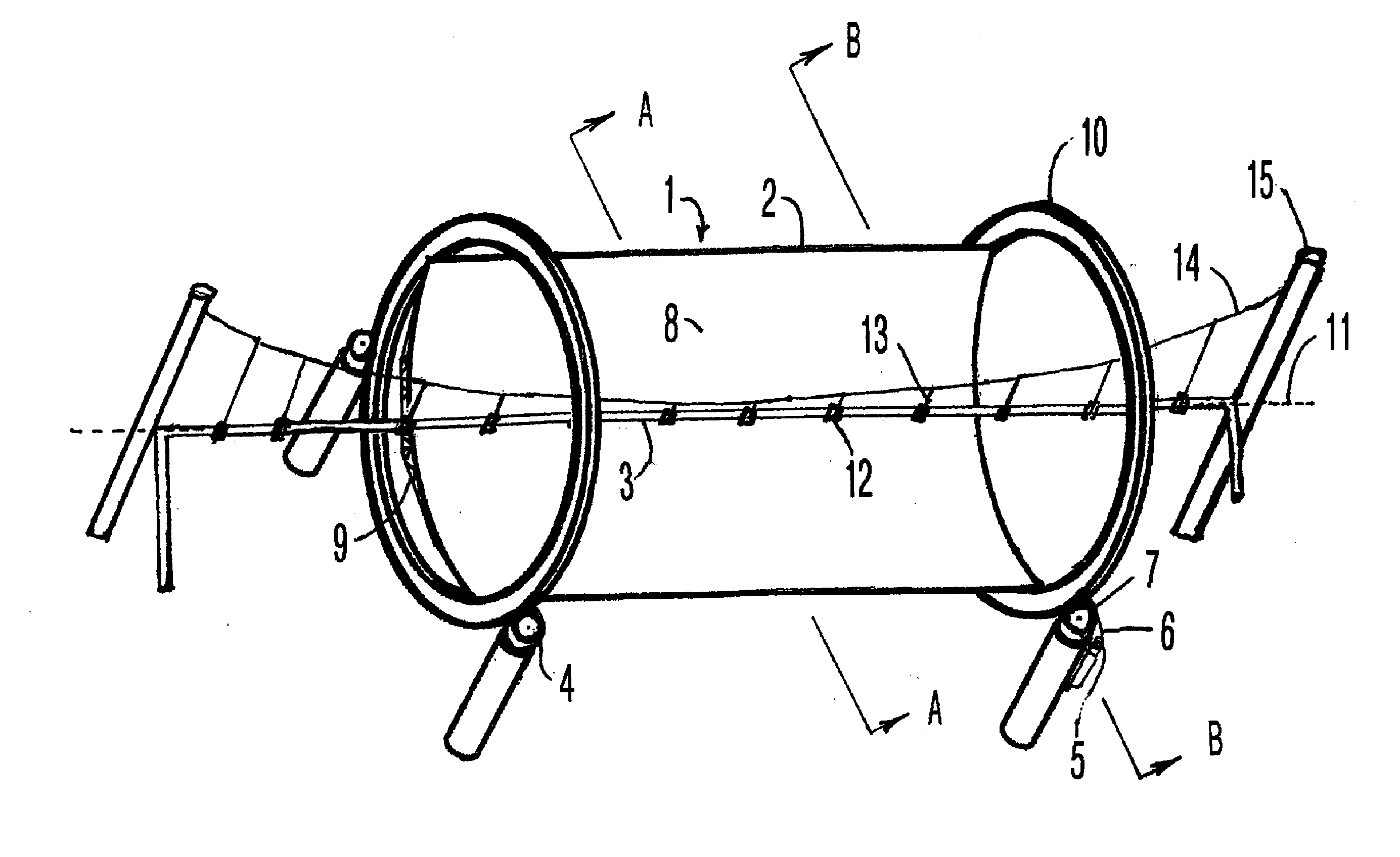
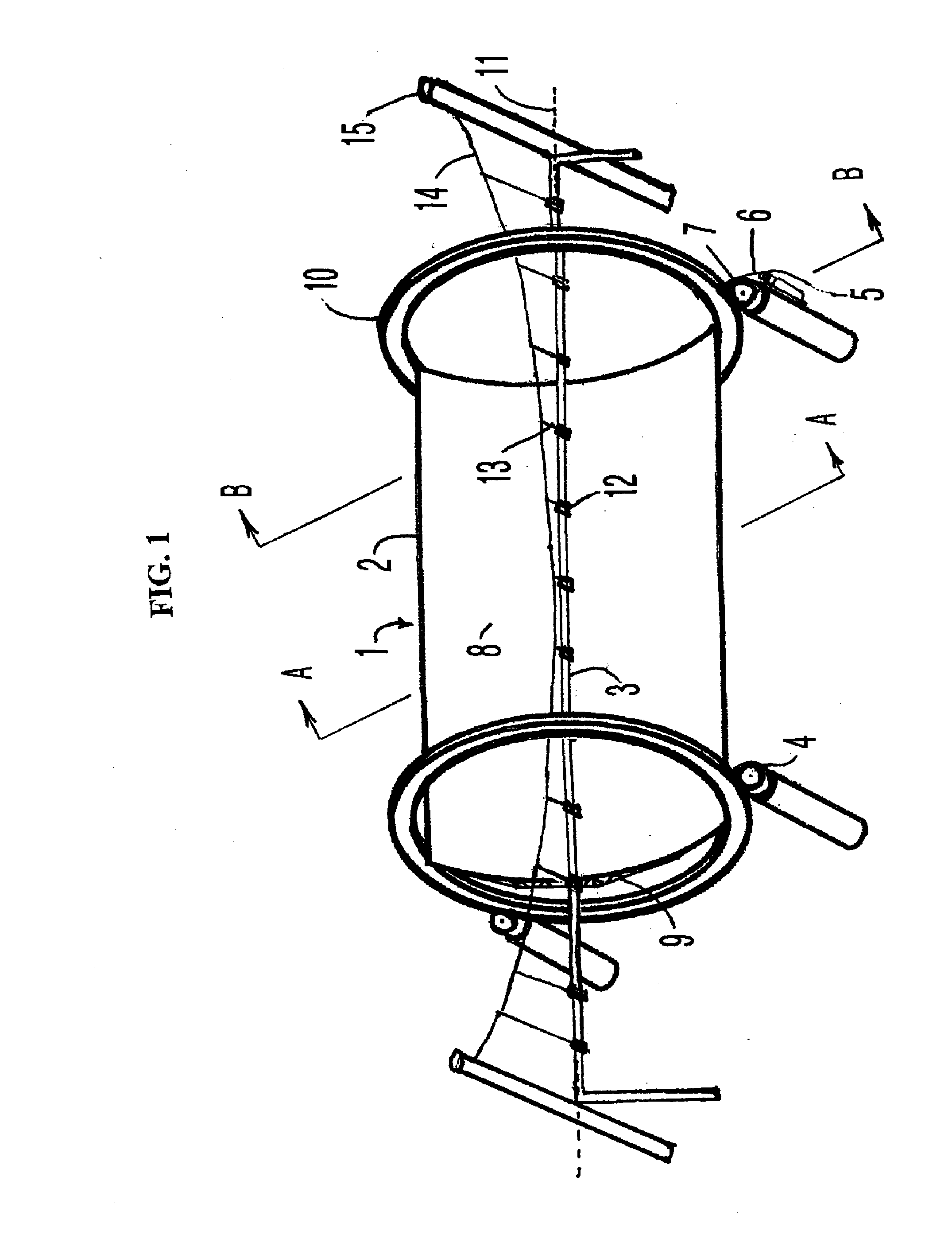
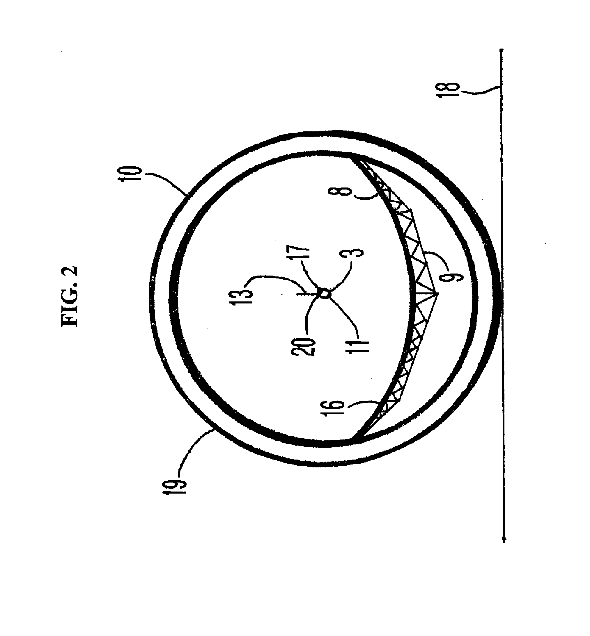
[0015]Referring to FIG. 1, a parabolic solar energy collector assembly 1 includes a parabolic reflector 2 which directs solar radiation to an independently supported collector tube 3. The parabolic reflector 2 rotates on support rollers 4 to track the travel of the sun, to optimize energy collection, and is driven by a drive system comprising a drive gear 5, engaged with a drive chain 6 connected to a drive roller 7. The parabolic reflector 2 is in the shape of a trough, and formed from a parabolic reflective surface 8 supported by a parabolic reflective surface support structure 9 supported by at least one circular support beam 10 which rides on the support rollers 4. In the embodiment of FIG. 1, two circular support beams are used though the number will depend on the length of the reflector, weight and other similar factors. Both the parabolic reflector 2 and the independent supported collector tube 3 are aligned along a generally North to South axis. The parabolic reflector 2 has...


PUM

PropertyMeasurementUnit
pressureaaaaaaaaaa
diameteraaaaaaaaaa
temperaturesaaaaaaaaaa

Abstract

A parabolic trough solar collector system has a parabolic reflector used with an independently supported collector tube. The parabolic reflector has a reflective surface formed on a reflective surface support structure, supported by a circular support beam. This assembly rests on a plurality of support and drive rollers supported by a roller support arm, supported by a roller support column. The parabolic reflector assembly rotates against the rollers along a single axis to maintain a focus line of the parabolic reflector surface at the same location as the center of the circle described by the outer edge of the circular support beam. Located at this same focus line is the independently supported collector tube not attached to the parabolic trough reflector. The collector tube is supported on pipe roller hangers, which in turn are supported by a wire catenary system connected to support towers which straddle the parabolic reflector.

Description

1. FIELD OF THE INVENTION[0001]The present invention relates to a parabolic trough solar collector system. More particularly, the present invention is a parabolic trough solar reflector with a servo controlled focusing means that allows a collector tube to remain stationary relative to the parabolic trough solar reflector while the parabolic trough solar reflector rotates independently from the independently supported collector tube.2. BACKGROUND[0002]Parabolic trough solar collectors systems generally comprise a horizontally extending reflector having a parabolic cross section, the reflector directing radiation from the sun to a horizontal focus line where a tubular conduit known as a collector tube is located. The collector tube is filled with a heat transfer fluid which is heated by the reflected solar radiation. The parabolic surface acts as a concentrator for directing an optimum amount of energy to the collector tube. Such parabolic trough solar collector systems are currently...

Claims


Application Information

Patent Timeline
Patent Type & Authority Applications(United States)
IPC IPC(8): F24J2/12F24S10/70F24S23/70F24S23/71F24S50/20
CPCF24J2/07F24J2/14F24J2/541Y02E10/41Y02E10/45Y02E10/47Y10T29/49826F24J2/12F24J2/24F24J2/5403Y10T29/49355Y10T29/49883B21D53/02F24S20/20F24S23/74F24S30/425F24S2030/14Y02E10/44F24S10/70F24S30/42Y02E10/40
Inventor JENNINGS, KEVIN
Owner JENNINGS KEVIN
Why Eureka
Try Eureka