Off-season start-ups to improve reliability of refrigerant system

a technology of refrigerant system and off-season start-up, which is applied in the direction of cooling fluid circulation, domestic cooling apparatus, lighting and heating apparatus, etc., can solve the problems of no longer present compressor damage, exacerbate the problem of potential compressor damage or its performance degradation, and achieve the effect of avoiding severe flood startups

Inactive Publication Date: 2010-01-21
CARRIER CORP
View PDF9 Cites 42 Cited by
  • Summary
  • Abstract
  • Description
  • Claims
  • Application Information

AI Technical Summary

Benefits of technology

[0005]Briefly, in accordance with one aspect of the invention, a timer is installed in communication with or integrated into the system control so as to periodically start the system during the off-season months to prevent the excessive migration of refrigerant to the compressor sump and thus eliminate severe flooded startups.

Problems solved by technology

If the system is then started up in the summer or spring with the compressor sump and other compressor elements being flooded with the refrigerant, the liquid refrigerant will slug through the compressor and can result in compressor damage.
Furthermore, after prolonged periods of time without the startups or even intermittent operation, all the residual lubricating oil which normally is collected on the compressor contact services during operation (i.e. bearings, scroll elements in the case of the scroll compressors, piston rings in the case of the reciprocal compressors, rotors in the case of the screw compressors, etc.) is no longer present and has been washed off by the refrigerant or completely drained from the surfaces.
Such conditions will exacerbate the problem of potential compressor damage or its performance degradation.
As also known, these flow control devices leak over time and there is still a significant volume of refrigerant trapped between the compressor and evaporator.
Also crankcase heaters present their own reliability problems, and may fail after several years of operation.
Crankcase heaters also add extra cost and reduce overall system efficiency.

Method used


Image

  • Off-season start-ups to improve reliability of refrigerant system
  • Off-season start-ups to improve reliability of refrigerant system

Examples


Embodiment Construction

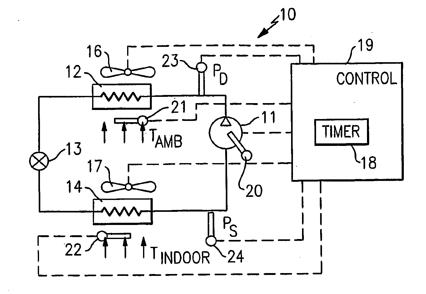
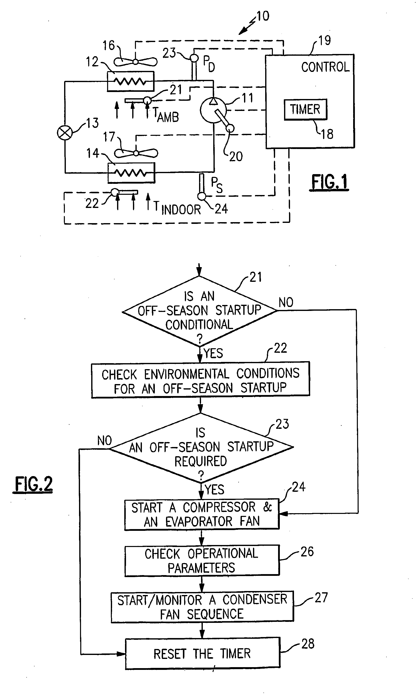
[0011]A basic vapor compression system 10 normally includes a compressor 11, a condenser 12, an expansion device 13 and an evaporator 14 interconnected in serial refrigerant flow communication.

[0012]A refrigerant vapor from the evaporator 14 is delivered to the compressor 11 where it is compressed, and the compressed vapor then flows to the condenser 12 where it is desuperheated, condensed and typically subcooled by a secondary fluid such as ambient air. Then the liquid refrigerant passes to the expansion device 13 where it is expanded to a lower pressure and temperature to form a two-phase (liquid and vapor) mixture with a portion of the refrigerant being flashed to a vapor. A vapor and liquid refrigerant mixture than passes to the evaporator 14 where it is evaporated and typically superheated by another secondary fluid such as air to be delivered to a conditioned space, while cooling this secondary fluid. The refrigerant vapor then passes to the compressor 11 to complete the cycle...


PUM


Abstract

A vapor compression system includes a timer and a controller for periodically starting up the system during the off-season periods (primarily non-cooling months) in which the system would normally be shut down. This provides periodic lubrication to the compressor components and prevents severe flooded starts due to excessive accumulation of refrigerant in the compressor (compressor oil sump in particular) and other system components. Provision is also made to sequentially turn on and off system components such as the compressor, the evaporator fan and the condenser fan to enhance the system operation. The timing sequences are provided for the time intervals between the startups, as well as the off-season operation cycle times.

Description

BACKGROUND OF THE INVENTION[0001]This invention relates generally to vapor compression systems and, more particularly, to a method and apparatus for preventing severe flooded starts caused by the system operational seasonality.[0002]A typical air conditioning system includes, in serial flow communication, a compressor, a condenser, an expansion device and an evaporator. The compressor compresses refrigerant and passes this high pressure refrigerant vapor to the condenser where it is desuperheated, condensed and typically subcooled, as a result of heat transfer interaction with a secondary fluid such as air or water. The liquid refrigerant then flows to the expansion device where it is expanded to a lower pressure and temperature forming a two-phase (liquid and vapor) refrigerant mixture at the expansion device exit, while a portion of the refrigerant is flashed to vapor. This vapor and liquid refrigerant mixture then flows to the evaporator, where heat is absorbed by the refrigerant...

Claims


Application Information

Patent Timeline
Patent Type & Authority Applications(United States)
IPC IPC(8): F25B1/00F25B49/02F25B39/04F25D17/06
CPCF25B31/002F25B49/02F25B2500/26F25B2600/01F25B2600/0251Y02B30/743F25B2600/112F25B2700/1931F25B2700/1933F25B2700/2104F25B2700/2106F25B2600/111F25B2400/01Y02B30/70
Inventor LIFSON, ALEXANDERTARAS, MICHAEL F.
Owner CARRIER CORP
Why Eureka
Try Eureka