Dispenser assembly

a technology of dispensing machine and assembly, which is applied in the field of dispensing machine, can solve the problems of occupying a large amount of floor space, affecting the movement of items, and affecting the quality of food, so as to reduce the risk of damage, reduce the risk of breakage, and slow down the movement of items

Inactive Publication Date: 2010-01-21
ADDCO NOMINEES
View PDF21 Cites 29 Cited by
  • Summary
  • Abstract
  • Description
  • Claims
  • Application Information

AI Technical Summary

Benefits of technology

[0041]The storage means may be adapted to enable glass or other breakable items to be stored and subsequently dispensed with a reduced risk of damage. The storage means may have buffered bends, shallow angles or other suitable means to enable glass items to be dispensed slowly, decreasing the risk of breakage.
[

Problems solved by technology

Unfortunately, conventional vending machines, and particularly those that include refrigeration, tend to be very large.
They often have a large footprint, take up a very large amount of floor space and are bulky above the footprint.
Often the machines create dead space above them that cannot be used, since the machine needs to stand on the floor.
Further, the requirements of refrigeration or heating of the products to be dispensed means that the vending machine and surrounding surfaces are of an unsuitable temperature for other goods to be displayed for sale eg hot or cold.
Therefore, conventional vending machines not only take up a large amount of space they also create unusable space around them that cannot be utilised for sale of items.
These machines tend to be wall mounted and for smaller, lighter items, but do not have sufficient capacity for most fast moving consumer goods, such canned beverages or o

Method used


Image

  • Dispenser assembly
  • Dispenser assembly
  • Dispenser assembly

Examples


first embodiment

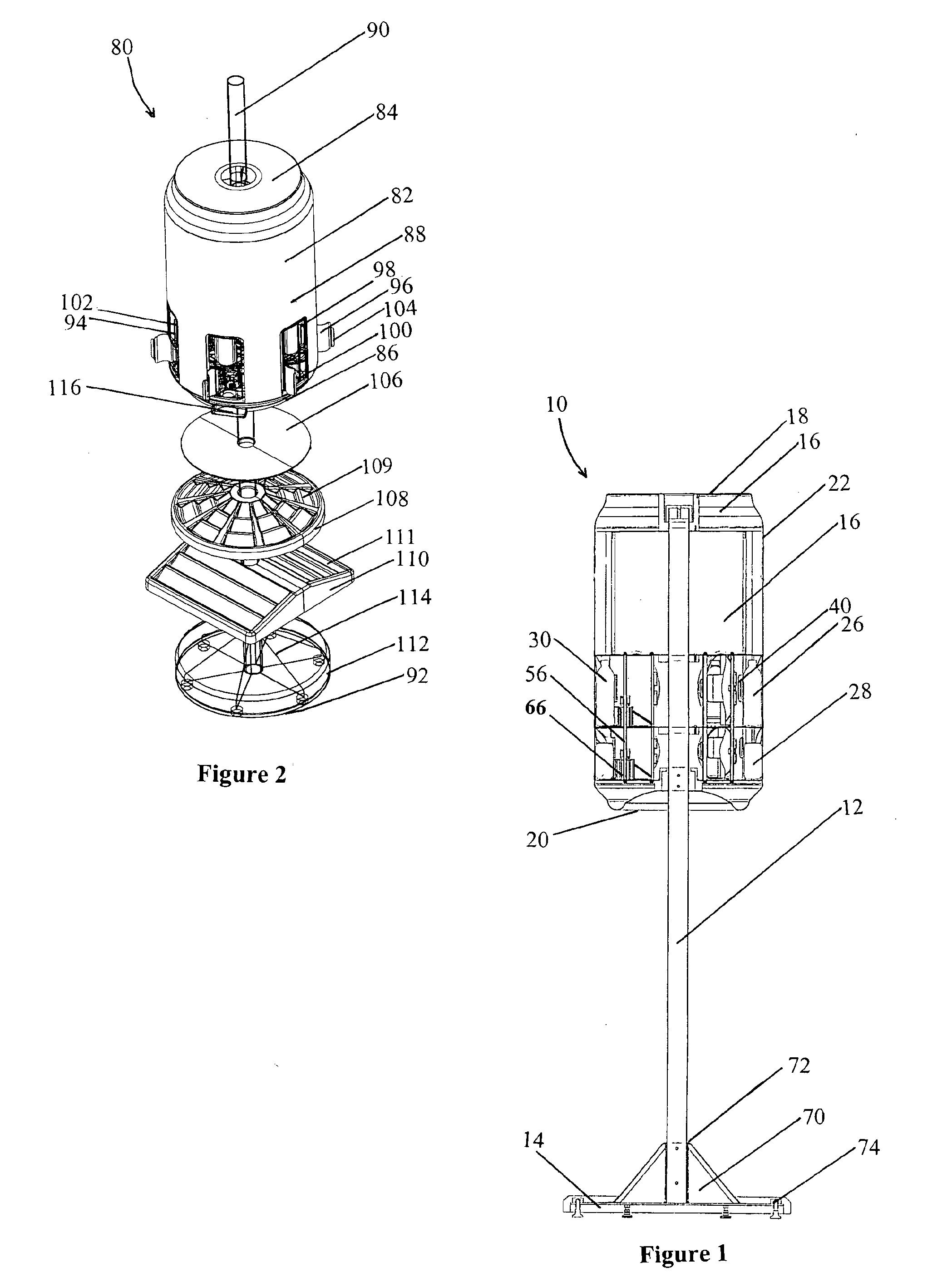
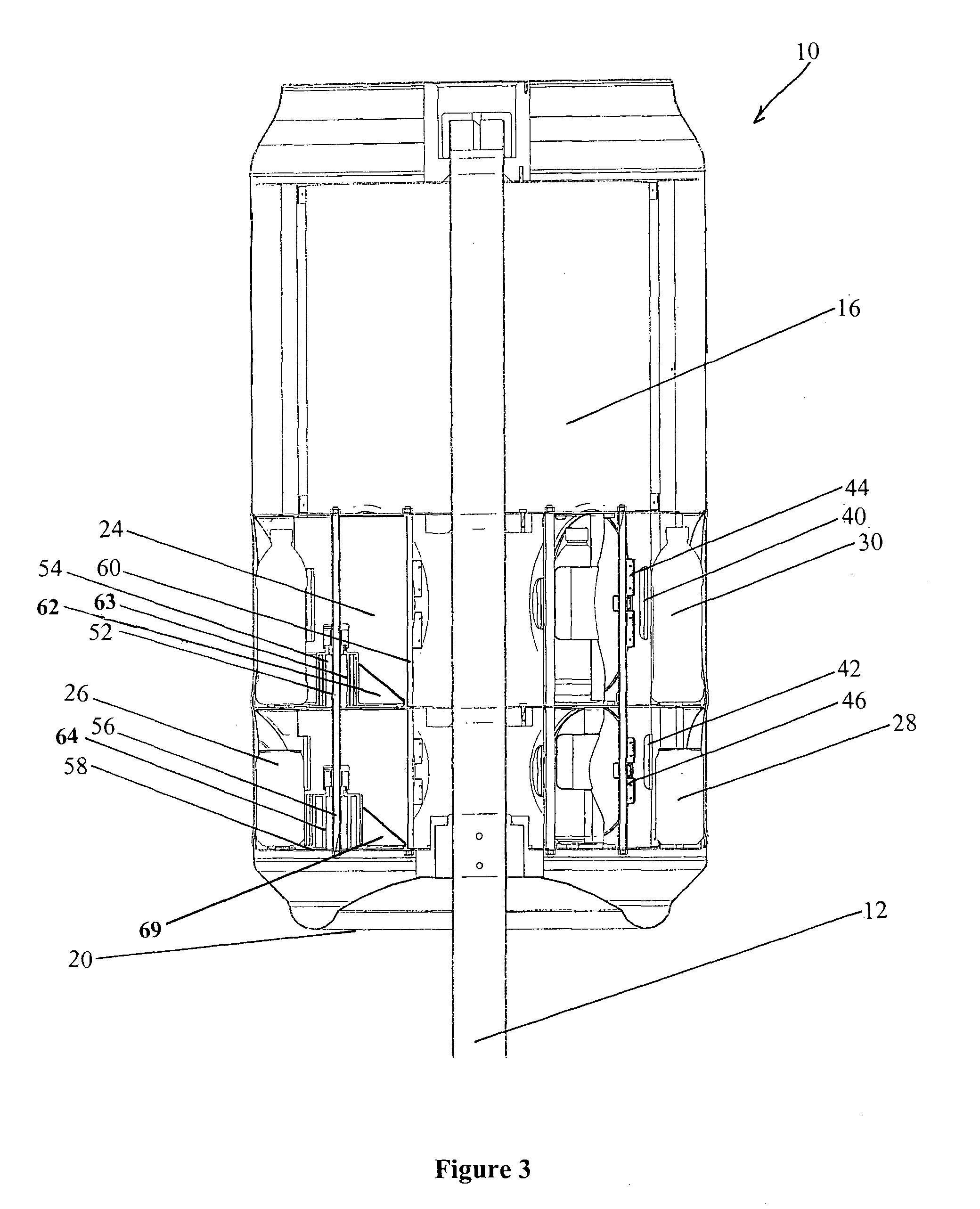
[0124]Holder 24, as illustrated, are cylindrical and configured for receipt of 6 cans 28 or 6 bottles 30. Holder 24 may be the same or different as appropriate for the type, kind, size, packaging or number of item 26, to be contained therein. Holder 24 are shown in main body 16 of dispenser 10 on bottom 20 of main body 16. As illustrated, 6 holder 24 surround pole 12, to form a layer of holders 24. The illustrated embodiment has two layers of holder 24, 12 in all, 6 in each group. Any suitable number of holders 24 or layers of holders 24 could be included to dispense item 26 as required. For example, refer to FIGS. 12b and 12c which illustrate a variation to the invention, having a taller body and three or four layers of holders. Please refer to the description below in this regard

[0125]Pairs of openings 32, 34 are illustrated in the main body 16 of dispenser 10 through which items 26 may be dispensed. There may be one pair of openings 32, 34 in a suitable, central, position or ther...

second embodiment

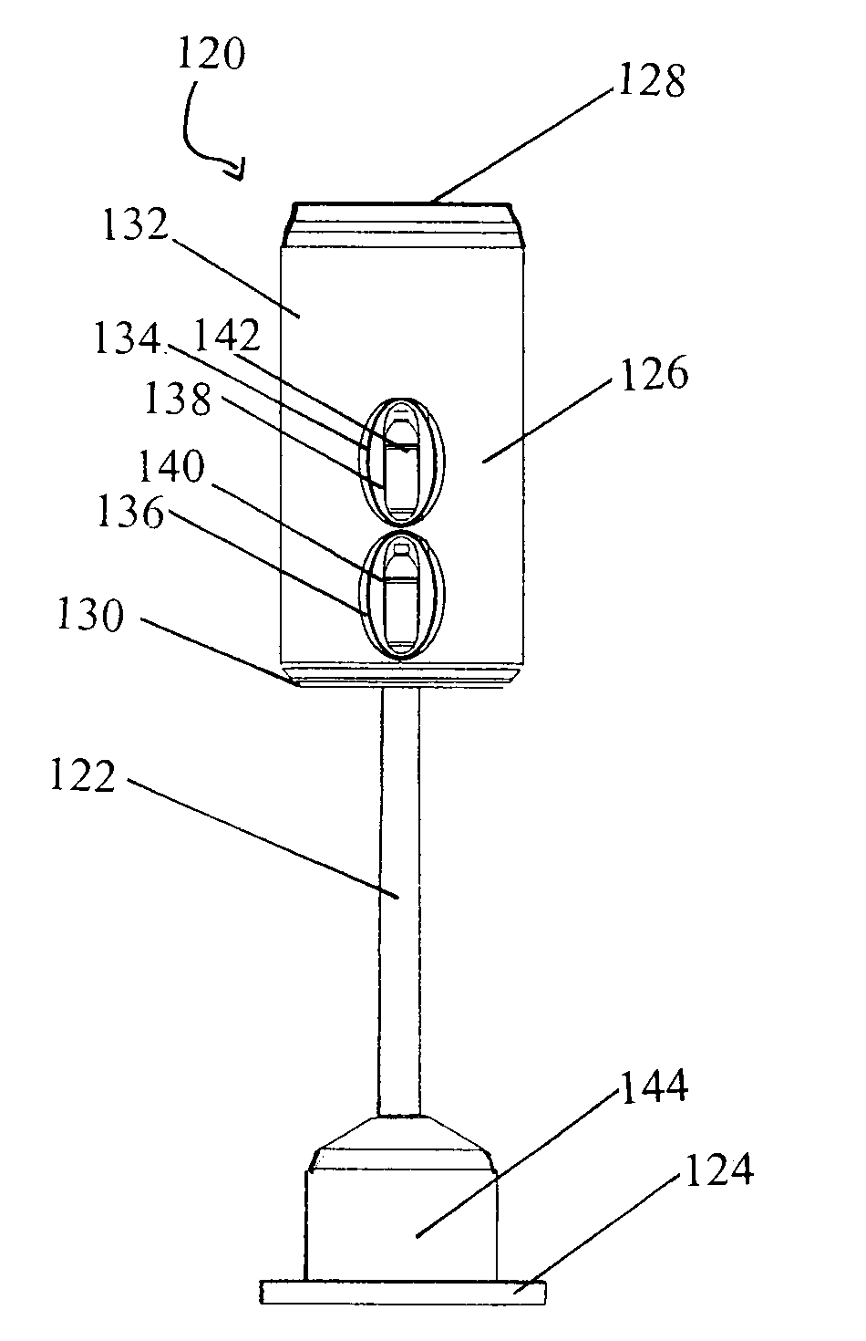
[0141]Referring to FIG. 2 the invention is illustrated, very similar to the first except for the particular configuration of the doors and the addition of shelves.

[0142]Dispenser 80 has main body 82 having top 84 and bottom 86 joined by body wall 88. Again, main body 82 looks like an enlarged can of drink. Dispenser 80 is mounted on pole 90, pole 90 being mounted on base 92. Pole 90 extends beyond top 84 through dispenser 80 and to base 92 in this embodiment. The internal workings are exactly the same as the first embodiment as illustrated in FIGS. 1, 3, 10, 11, 13 and 19 referred to above. Two square doors 94, 96 can be seen for each rectangular opening 98, 100. Doors 94, 96 have handles 102, 104 so a person can access cans 28 through opening 98, 100. Dispensing and restocking occurs as described for the first embodiment.

[0143]Door 116 is included for dispensing a different type or kind of item, for example, using a gravity fed stack of chocolate bars.

[0144]FIG. 2 illustrates a pre...

embodiment 1

[0172]In an alternative form of the invention, the opening lies in the bottom of main body. The shape of the main body is similar to embodiment 1 and is similarly mounted on a pole which in turn is mounted on a base.

[0173]In this alternative form of the invention (not shown) instead of doors and opening being located in the wall of the main body of the dispenser, flaps are attached along a long edge of an opening in the bottom of the main body. It is through these flaps and the opening that items may be dispensed from storage means. When an item has been dispensed, the next item moves close to the opening and flaps ready to be dispensed. There may be any number of flaps and these may be made of any suitable material, for example plastic. The flaps may be attached to an opening by any suitable means such as hinges. The flaps in this form of the invention can act to maintain the items in the body of the dispenser until one item is dispensed and a new item is required.

[0174]In this for...


PUM


Abstract

A dispenser (10) for items (26), such as cans (28) or bottles (30), including a main body (16) including one or more openings (32,34) for item dispensing therethrough; a storage means such as a holder (24) included in the main body to store the items substantially within the main body; and a rotation device (54,66) to rotate substantially within the main body, wherein items are presented by the rotation device to one or more of the openings for dispensing.

Description

CROSS-REFERENCE TO RELATED APPLICATIONS[0001]The present application claims priority to International Application No. PCT / AU2007 / 001284 which was filed on Aug. 31, 2007 and claims priority to Australian Provisional Patent Application No. 2006904760 filed Aug. 31, 2006 and Australian Provisional Patent Application No. 2006907090 Dec. 20, 2006.STATEMENT RE: FEDERALLY SPONSORED RESEARCH / DEVELOPMENT[0002]Not ApplicableBACKGROUND[0003]1. Technical Field[0004]This invention relates to a dispenser of items, and in particular to a dispenser of chilled or non-chilled fast moving consumer goods, such as canned or bottled drinks, ice lollies, ice-creams, chocolate bars, snacks, sandwiches, hot chips, pies, hot dogs and fast foods, for example.[0005]A dispenser has been developed and described in Australian provisional patent application numbers 2006904760 and 2006907090, from both of which priority has been claimed and the entire contents of which are incorporated herein by reference.[0006]2. ...

Claims


Application Information

Patent Timeline
IPC IPC(8): A47F1/08A47F3/04B65G59/00
CPCA47F1/08A47F1/12A47F3/02G07F11/54A47F5/05A47F5/06A47F5/02A47F3/04A47F3/0417A47F3/11
Inventor FREEDMAN, WILLIAM
Owner ADDCO NOMINEES
Why Eureka
Try Eureka