Novel scintillation detector array and associate signal processing method for gamma ray detection with encoding the energy, position, and time coordinaties of the interaction

a detector array and gamma ray detection technology, applied in the field of new scintillation detector array and associate signal processing method for gamma ray detection, can solve the problems of reducing system efficiency, patent does not teach whether and how to use light guides, and image resolution degradation

Inactive Publication Date: 2010-01-21
YU WANG
View PDF8 Cites 40 Cited by
  • Summary
  • Abstract
  • Description
  • Claims
  • Application Information

AI Technical Summary

Problems solved by technology

Photons impinging upon such detector systems at angles other than normal may traverse the path of several scintillation crystals, resulting in uncertainty of their trajectory lines, thereby degrading the image resolution due to parallax error.
However, this patent does not teach whether and how a light guide can be used to distribute scintillation light over a plurality of photodetectors.
Although this method is capable of providing the transverse and longitudinal position coordinates of photon interactions in scintillation crystal detector systems, it will result in reduced system efficiency if the overall scintillator depth is kept constant for two different scintillator materials—i.e., each of the two different scintillation layers is thinner.
On the other hand, if the scintillators are increased in length (i.e., thicker) to compensate for the efficiency loss, then the system resolution will be degraded.
This approach has the undesired effect of reducing the total collected scintillation light and causing the Compton continuum of the high light yield scintillator to overlap with the photopeak region of the low light yield scintillator.
The result is inherent uncertainty in the contribution of scatter to the full energy photopeak.
This calibration method is difficult to implement for large arrays of scintillators.
Therefore, when the gains of photodetectors are not well equalized, the scintillator position histogram will distort two-dimensionally in an unpredictable manner.
As a result, it is difficulty to know which scintillators, among the photodetectors within a gamma detector array, have their position histogram that is insensitive to the gain variations.
This makes it impossible to use energy spectrum / spectra of one or more scintillators to perform gain equalization in a timely manner (for instance, everyday or even during a patient scan), when the gains are unbalanced to an unacceptable extent, e.g. the variation of the gains is more than 10%.
Despite these changes, the continuous slab of NaI(Tl) scintillator detector designs are inferior to PET specific detector designs in terms of system performance.

Method used


Image

  • Novel scintillation detector array and associate signal processing method for gamma ray detection with encoding the energy, position, and time coordinaties of the interaction
  • Novel scintillation detector array and associate signal processing method for gamma ray detection with encoding the energy, position, and time coordinaties of the interaction
  • Novel scintillation detector array and associate signal processing method for gamma ray detection with encoding the energy, position, and time coordinaties of the interaction

Examples


Embodiment Construction

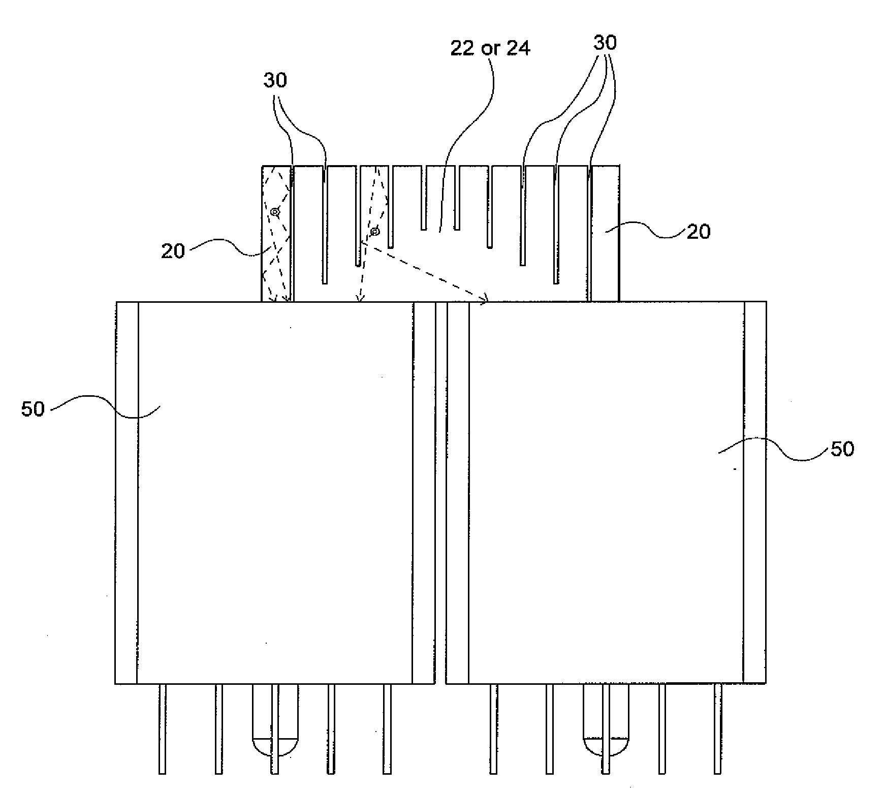
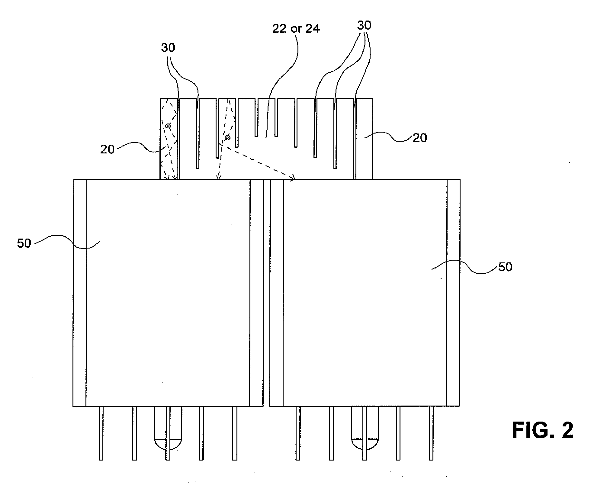
[0035]Embodiments of the invention relate to detectors and apparatus that can determine the energy, position and time coordinates of light emission generated by interactions between gamma rays and scintillators comprising one or more scintillating materials. Some embodiments of the invention relate to gamma detector arrays that comprise scintillator detectors (for interaction with gamma rays) coupled to photodetectors (for detection of photons generated from gamma ray interactions with the scintillator detectors). Some scintillator detectors may be optically coupled to photodetectors using a light guide, which may be segmented or non-segmented. In addition, the light guide may be active (with scintillating capability) or non-active (without scintillating capability). “Segmented” or “non-segmented” refers to whether the light guide has barriers defining a number of slots. Such segmented slots may have barriers at different depth to allow for control of statistical distributions of ph...


PUM


Abstract

A gamma ray detector module includes at least one scintillation detector configured to operate in a dot-decoding mode, or at least two scintillation detectors configured to operate in a line-decoding mode, wherein the at least one scintillation detector is each coupled to a single photodetector, and wherein the at least two scintillation detectors are coupled to at least two photodetectors arranged substantially along a line; and at least four scintillation detectors configured to operate in a plane-decoding mode, wherein the at least four scintillation detectors are coupled to a plurality of photodetectors arranged in a two-dimensional array.

Description

BACKGROUND[0001]Devices for detecting the distribution of gamma rays transmitted or emitted through objects to study the compositions or functions of the objects are well known. These devices are typically used in Emission Computed Tomography, which can be divided into two specific classes: Single Photon Emission Computed Tomography (SPECT), which uses radiotracers that emit gamma rays but do not emit positrons, and Positron Emission Tomography (PET), which uses radiotracers that emit positrons. The fundamental physical difference between the two techniques is that PET uses annihilation coincidence detection, and SPECT does not.[0002]PET can determine, in-vivo, biochemical functions, after injection of biochemical analog radiotracer molecules that emit positrons in a living body. The positrons annihilate with surrounding electrons in the subject body to produce a pair of gamma-rays, each having 511 keV of photon energy traveling in nearly opposite directions. The detection of a pair...

Claims


Application Information

Patent Timeline
Patent Type & Authority Applications(United States)
IPC IPC(8): G01T1/161G01T1/20
CPCG01T1/1642A61B6/037G01T1/1644
Inventor WANG, YU
Owner YU WANG
Why Eureka
Try Eureka