Hybrid engine installation and a method of controlling such an engine installation

a hybrid engine and installation method technology, applied in the direction of electric motor starters, efficient propulsion technologies, electric energy vehicles, etc., can solve the problems of destroying the gas turbine, reducing the fuel consumption of the free-turbine gas turbine, and affecting the performance of the engine, so as to achieve the effect of limiting the fuel consumption

Active Publication Date: 2010-01-21
EUROCOPTER
View PDF8 Cites 78 Cited by
  • Summary
  • Abstract
  • Description
  • Claims
  • Application Information

AI Technical Summary

Benefits of technology

[0023]An object of the present invention is thus to limit fuel consumption in an engine installation by proposing a novel type of engine installation.

Problems solved by technology

Although effective, linked-turbine gas turbines suffer from a pumping phenomenon.
The blades of the linked turbine are then melted almost immediately, thereby destroying the gas turbine.
Nevertheless, the fuel consumption of a free-turbine gas turbine is relatively high.
Thus, for most of the time, the gas turbine is delivering power that is remote from its maximum power, thereby leading to increased fuel consumption.

Method used


Image

  • Hybrid engine installation and a method of controlling such an engine installation
  • Hybrid engine installation and a method of controlling such an engine installation
  • Hybrid engine installation and a method of controlling such an engine installation

Examples


first embodiment

[0106]With reference to FIG. 1, in a first embodiment, the coupling means 30 comprises an internal overrunning clutch or freewheel 40.

[0107]This internal freewheel 40 is thus provided firstly with a driving inner portion 41 secured to the outside surface 23 of the working shaft 22, and secondly with a driven outer portion 42 secured to the inside surface 17 of the main shaft 14.

[0108]The internal freewheel 40 is of conventional type, being a ratchet freewheel or a freewheel having a plurality of rollers and ramps. The nature of the internal freewheel is thus not limiting in any way.

[0109]Thus, the working shaft 22 is suitable for driving the main shaft 14 in rotation, with the working and main shafts 22 and 14 then rotating at the same speed of rotation.

[0110]In contrast, if the main shaft 14 rotates faster than the working shaft 22, then the working shaft 22 can no longer drive the main shaft 14 mechanically because of the internal freewheel.

[0111]This first embodiment is thus part...

second embodiment

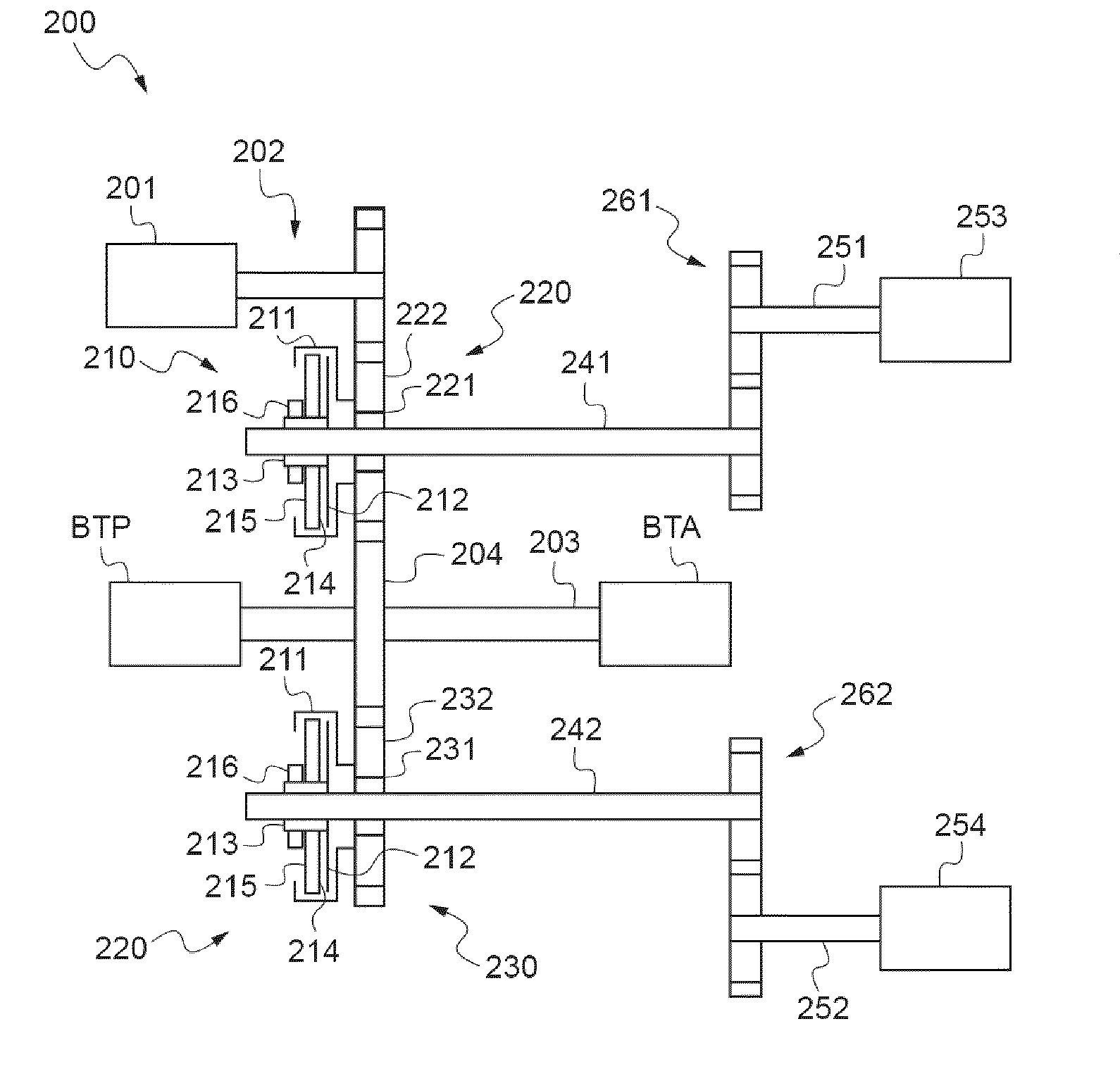
[0113]With reference to FIG. 2, in the second embodiment, the coupling means 30 comprise a drive system 50 and an internal clutch 60 controlled by the regulator member 80 of the combination gas turbine 1.

[0114]It will be understood, that because of the drive system 50, it is possible, by organizing the various mechanical parts of said drive system in an appropriate manner (not shown), to couple together a working shaft 22 and a main shaft 14 that have opposite directions of rotation.

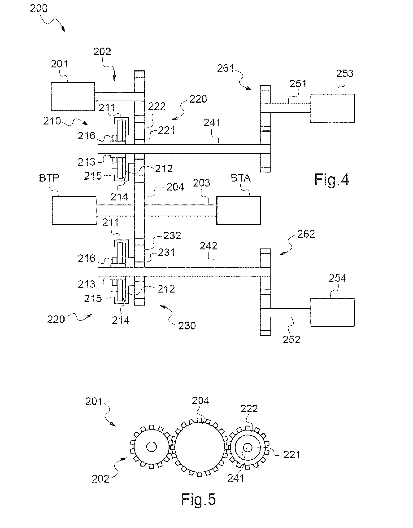
[0115]The drive system shown by way of example comprises a first main gearwheel 14′ secured to the main shaft 14 and meshing with a first link gearwheel 51.

[0116]The first link gearwheel 51 is fastened to a link shaft 53 that passes through a second link gearwheel 52, the second link gearwheel 52 meshing with a second main gearwheel 22′ secured to the working shaft 22.

[0117]Under such circumstances, the coupling means 30 is provided with an internal clutch 60 suitable for linking the link shaft 53 to the...


PUM


Abstract

A hybrid engine installation (200) includes drive element (204) suitable for driving a mechanical element (BTP, BTA) in rotation. In addition, the hybrid engine installation is remarkable in that it includes at least one gas turbine (253, 254) and at least one electric motor (201) mechanically linked to the drive element (204) to drive it in rotation.

Description

FIELD OF THE INVENTION[0001]The present invention relates to an engine installation and to a method of controlling such an engine installation.[0002]The purpose of the engine installation is to drive a mechanical element in rotation, e.g. a power transmission gearbox of a rotorcraft, with the help of at least one gas turbine.[0003]Consequently, the technical field of the invention is that of engine installations including a gas turbine.BACKGROUND OF THE INVENTION[0004]In order to drive the main lift and propulsion rotor of a rotorcraft, in particular via a main power transmission gearbox, a first engine installation is known that implements a gas turbine referred to as a “linked-turbine” gas turbine.[0005]A linked-turbine gas turbine is provided with a gas generator comprising in succession at least one compressor, a combustion chamber, and at least one expansion turbine, the compressor being mechanically linked to the expansion turbine via a main shaft.[0006]It is possible to fit t...

Claims


Application Information

Patent Timeline
Patent Type & Authority Applications(United States)
IPC IPC(8): H02P9/04F02C3/10F02C3/00H02K23/52
CPCY02T10/6221F05D2270/58Y02T50/64B60K6/24B60K6/383B60K6/387B60K6/48B60W2710/06B64C27/04B64D27/10B64D27/24B64D35/02B64D35/08F01D15/12F02C3/107F02C7/268F02C7/36F05D2260/4023Y02T10/6295B60L7/14B60L15/20B60L15/2009B60L50/16B60L2220/14B60L2220/16B60L2240/421B60L2240/486B60L2240/507B60L2260/16Y02T10/62Y02T10/64Y02T10/7072Y02T10/72Y02T50/60Y02T10/70
Inventor CERTAIN, BERNARD
Owner EUROCOPTER
Why Eureka
Try Eureka