Fuel direct injection in cylinder liquefied petroleum gas engines

A technology of liquefied petroleum gas and in-cylinder direct injection, applied to internal combustion piston engines, engine components, engine control, etc., can solve the problem of limiting engine performance and improving gas economy, limiting the response speed of liquefied petroleum gas supply and combustion control, Affect the engine charging efficiency and other issues to achieve the effect of improving performance and increasing output

Inactive Publication Date: 2008-05-21
CHERY AUTOMOBILE CO LTD
View PDF0 Cites 0 Cited by
  • Summary
  • Abstract
  • Description
  • Claims
  • Application Information

AI Technical Summary

Problems solved by technology

[0002] At present, the liquefied petroleum gas engines on the market mostly use multi-point electronic gas injection. Liquefied petroleum gas (LPG) is injected into the intake passage of each cylinder, mixed with air in the air passage, and then enters the cylinder, which limits the use of liquefied petroleum gas to a certain extent. The response speed of gas supply and combustion control, thus limiting the improvement of engine performance and gas economy
In addition, because the liquefied petroleum gas is evaporated by the decompression evaporator before injection, what the ordinary liquefied petroleum gas engine injects into the airway is gas, which greatly affects the charging efficiency of the engine.

Method used


Image

  • Fuel direct injection in cylinder liquefied petroleum gas engines

Examples


Embodiment Construction

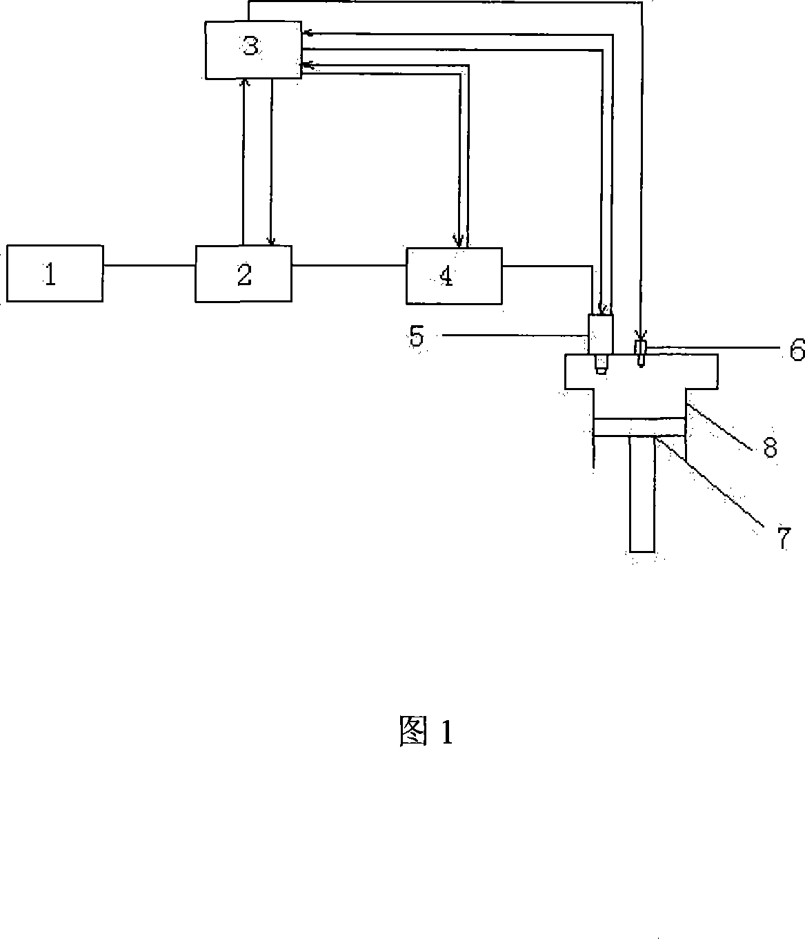
[0009] The present invention will be further described below in conjunction with the accompanying drawings:

[0010] As shown in the figure, it has a gas nozzle 5, a spark plug 6, an LPG (liquefied petroleum gas) storage device 1, a solenoid valve 2, an LPG booster device 4, an LPG storage device, a solenoid valve, an LPG booster device, and a gas nozzle via The pipelines are connected in sequence; it also has an ECU (vehicle computer) 3 that can adjust the LPG booster device; the ECU can also adjust the gas nozzle 5, the spark plug 6, and the solenoid valve 2; it also has a cylinder block 8 and a piston 7.

[0011] During operation, the liquefied petroleum gas flows out through the LPG storage device 1, and reaches the LPG booster device 4 through the solenoid valve 2. The LPG booster device controls the LPG pressure at about 5Mpa, and then directly injects it into the cylinder 8 through the gas nozzle 5. ECU 3 controls the LPG booster, gas nozzles, spark plugs, and solenoid ...


PUM


Abstract

The present invention relates to a direct-injection LPG engine, which can effectively decrease the gas consumption and drainage and improve the engine performance. The technical proposal is that: the direct-injection LPG engine includes a gas nozzle and a spark plug. The present invention is characterized in that the engine also includes a LPG storing device, an electromagnetic valve and a LPG pressurizing device; the LPG storing device, the electromagnetic valve, the LPG pressurizing device and the gas nozzle are connected one by one along a pipeline. As the LPG never goes through an air inlet canal, the direct-injection structure adopted by the present invention will not affect the charging efficiency, thus increasing the output to the large extent, controlling the drainage and oil consumption and significantly improving the engine performance far exceeding the LPG engines with the same delivery capacity.

Description

technical field [0001] The invention relates to an engine, in particular to an engine capable of directly injecting liquefied petroleum gas in a cylinder. Background technique [0002] At present, LPG engines on the market mostly use multi-point electronic gas injection. LPG is injected into the intake passage of each cylinder, mixed with air in the air passage, and then enters the cylinder, which limits LPG to a certain extent. The responsiveness of the gas supply and combustion control limits the improvement in engine performance and gas economy. In addition, because the liquefied petroleum gas is decompressed and evaporated by the decompression evaporator before injection, the ordinary liquefied petroleum gas engine injects gas into the air passage, which greatly affects the charging efficiency of the engine. SUMMARY OF THE INVENTION [0003] The purpose of the present invention is to provide an in-cylinder direct injection LPG engine capable of effectively reducing ga...

Claims


Application Information

Patent Timeline
Patent Type & Authority Applications(China)
IPC IPC(8): F02M21/02F02D43/00
CPCY02T10/32Y02T10/30
Inventor 项发青
Owner CHERY AUTOMOBILE CO LTD
Why Eureka
Try Eureka