Power transmission control device, power transmission device, power receiving control device, power receiving device, and electronic apparatus

a power transmission device and control device technology, applied in the direction of switch power arrangement, contact mechanism, relay, etc., can solve the problems of inability to achieve data communication between the power transmission side host and the application level, and achieve the effect of reducing the processing load of the power receiving-side hos

Active Publication Date: 2010-01-21
138 EAST LCD ADVANCEMENTS LTD
View PDF8 Cites 119 Cited by
  • Summary
  • Abstract
  • Description
  • Claims
  • Application Information

AI Technical Summary

Benefits of technology

[0010]The power transmission control device includes the host interface communicating with the power transmission-side host and the register section accessible by the power transmission-side host via the host interface. When the power transmission-side host writes a communication request command in the register section via the host interface, the controller shifts into the communication mode executing inter-host communication, and the communication request command is transmitted to the power receiving device. In this manner, contactless power transmission can be effectively utilized to execute appropriate data communication between the power transmission-side host and the power receiving-side host.
[0044]In this manner, until the command reception is notified, the power receiving-side host can execute other processing, thereby enabling a processing load of the power receiving-side host to be reduced, for example.

Problems solved by technology

Thus, in the above technique, for appropriate contactless power transmission between the power transmission side device and the power receiving side device, transmission of an authentication code is executed, whereas the technique is not ready for data transmission at an application level higher than that.
Accordingly, there has yet been no method for achieving data communication between a power transmission side host and a power receiving side host, for example, by effectively utilizing a charging time of an electronic apparatus.

Method used


Image

  • Power transmission control device, power transmission device, power receiving control device, power receiving device, and electronic apparatus
  • Power transmission control device, power transmission device, power receiving control device, power receiving device, and electronic apparatus
  • Power transmission control device, power transmission device, power receiving control device, power receiving device, and electronic apparatus

Examples


Embodiment Construction

[0065]Embodiments of the invention will be described in detail. The embodiments below do not unduly restrict the scope of the invention claimed, and all of structures included in description of the embodiments are not necessarily essential to the invention.

[0066]1. Electronic Apparatus

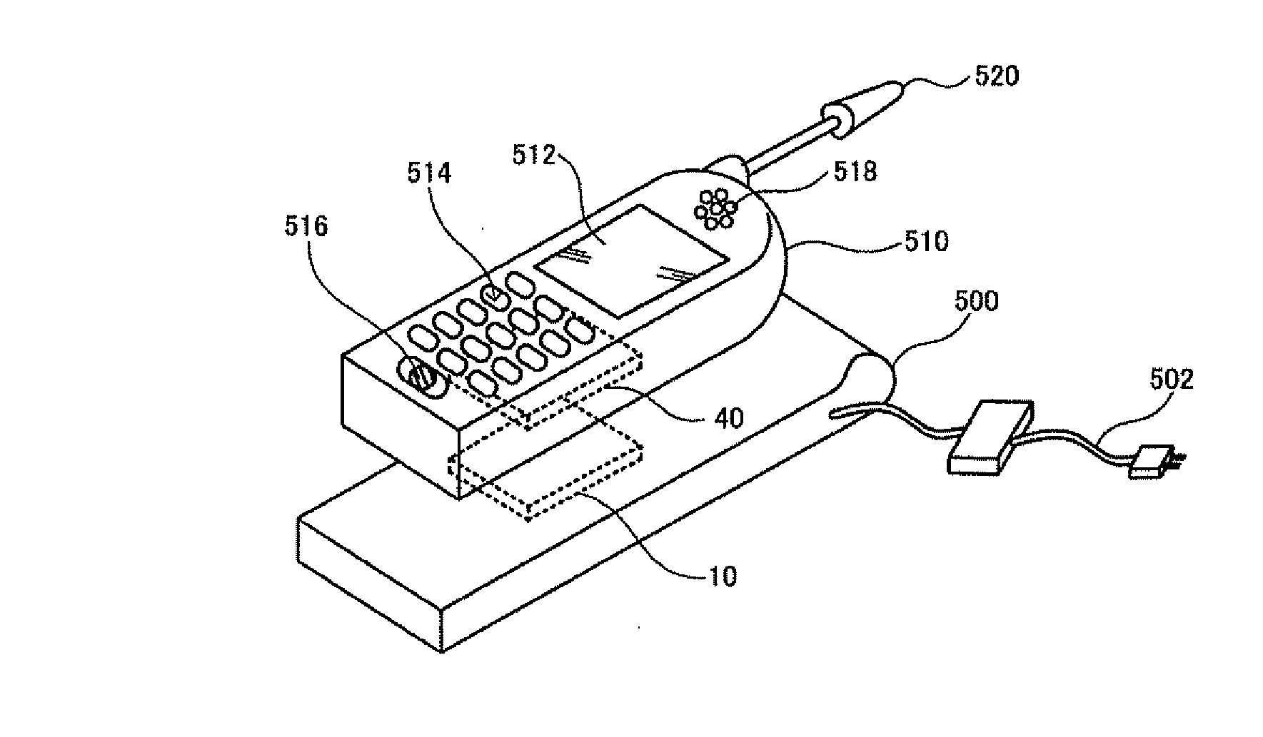
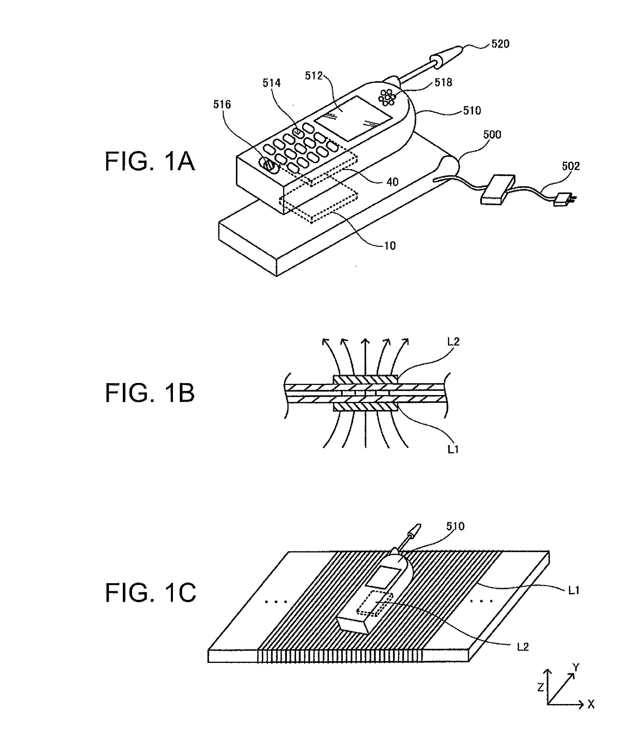
[0067]FIG. 1A shows examples of an electronic apparatus applying a contactless power transmission system according to an embodiment of the invention. A charger 500 (a cradle) as an example of the electronic apparatus includes a power transmission device 10. A mobile phone 510 as another example of the electronic apparatus includes a power receiving device 40. The mobile phone 510 further includes a display section 512 such as a liquid crystal display (LCD), a operating section 514 with buttons or the like, a microphone 516 (a speech sound inputting section), a speaker 518 (a speech sound outputting section), and an antenna 520.

[0068]The charger 500 receives power via an AC adapter 502. The power suppli...


PUM

PropertyMeasurementUnit
voltageaaaaaaaaaa
poweraaaaaaaaaa
data transmissionaaaaaaaaaa

Abstract

There is provided a power transmission control device included in a power transmission device in a contactless power transmission system that transmits power from the power transmission device to a power receiving device by electromagnetically coupling a primary coil to a secondary coil to supply the power to a load of the power receiving device. The power transmission control device includes a controller controlling the power transmission control device, a host interface communicating with a power transmission-side host, and a register section accessible from the power transmission-side host via the host interface. The controller shifts into a communication mode that executes communication between the power transmission-side host and a power receiving-side host, when the power transmission-side host writes, via the host interface, a communication request command that requests the communication between the hosts in the register section. Then, the controller transmits the communication request command to the power receiving device.

Description

[0001]The present application claims a priority based on Japanese Patent Application No. 2008-185396 filed on Jul. 16, 2008, the contents of which are incorporated herein by reference.BACKGROUND[0002]1. Technical Field[0003]The present invention relates to a power transmission control device, a power transmission device, a power receiving control device, a power receiving device, and an electronic apparatus.[0004]2. Related Art[0005]Recently, contactless power transmission (non-contact power transmission) has been highlighted as a technique allowing power transmission using electromagnetic induction, without contact between metal portions. For example, there is a disclosed technique in which the contactless power transmission is applied to charging of mobile phones and household appliances, such as a cordless handset of a phone system.[0006]JP-A-2006-60909 is an example of related art regarding the contactless power transmission. In this technique, an authentication code is transmit...

Claims


Application Information

Patent Timeline
Patent Type & Authority Applications(United States)
IPC IPC(8): H01F38/00H02J7/00
CPCH02J7/025H01F2038/143H02J50/10H02J7/00034H02J50/90H02J50/60H02J50/80H02J50/12
Inventor KAMIYAMA, MASAYUKIONISHI, KOTASHIOZAKI, NOBUTAKAYODA, KENTAROKAMIJO, TAKAHIRO
Owner 138 EAST LCD ADVANCEMENTS LTD
Why Eureka
Try Eureka