Device and Method for Processing a Real Subband Signal for Reducing Aliasing Effects

a technology of subband signal and real subband, applied in the field of real subband signal processing for reducing aliasing effects, can solve the problems of inconvenient encoding, inability to reduce aliasing, and relatively long filtering, so as to reduce aliasing, reduce aliasing, and reduce the effect of filter length

Active Publication Date: 2010-01-21
FRAUNHOFER GESELLSCHAFT ZUR FOERDERUNG DER ANGEWANDTEN FORSCHUNG EV
View PDF14 Cites 25 Cited by
  • Summary
  • Abstract
  • Description
  • Claims
  • Application Information

AI Technical Summary

Benefits of technology

[0025]The present invention is based on the finding that the problems of high artefacts or, in exchange for this, great filter lengths can be solved by dividing subband filtering to a normal portion including a subband weighted by a weighting factor for a special subband, and a correction portion depending on another subband and a weighting factor for the other subband. Thus, an efficient implementation is achieved, since long filters for generating a normal portion are no longer necessary according to the invention, since this normal portion is no longer filtered “back and forth”, but simply weighted. The aliasing problem is solved using the correction portion calculated in dependence on another subband which will, for example, be the neighboring subband, and in dependence on a weighting factor for this subband. In order to render the inventively weighted subband “aliasing-proof”, the correction portion is combined with the weighted subband, such as, for example, added, to obtain a corrected subband signal resulting in reduced aliasing.
[0026]The present invention is of advantage in that the main portion of the corrected subband signal is calculated directly, i.e. only using weighting of the weighting factor provided for this subband signal, and not subjected to filtering. This saves calculating time and, at the same time, calculating power, which is especially important, in particular for mobile or battery-driven apparatuses. No more filtering of the subband itself by means of a long analysis filter and subsequent synthesis filter may be used. Instead, only sample after sample has to be weighted. This is achieved by a division into the weighted portion and the correction term.

Problems solved by technology

The result may be audible interferences, such as, for example, by amplitude modulation.
However, if the two signals x0, x1 are amplified differently, the portion of the signal components in the overlapping region will also be amplified differently, the result of which is that the receive signal y(n) has more aliasing since the synthesis filter bank “has not expected” a different weighting for the two overlapping filters.
Such artefacts can be avoided by using complex-value filter banks which, however, do not comprise critical sampling and are thus not suitable for encoding.
However, this solution is, as has been mentioned, very complicated since, in contrast to a direct manipulation of FIG. 5, an additional complex analysis filter bank and an additional complex synthesis filter bank may be used, these filter banks being complicated from a calculating point of view and resulting in a delay since the analysis filters and / or synthesis filters comprise considerable filter lengths which may really be in a range of more than 30 filter taps per filter bank, i.e. may be on both the analysis side and the synthesis side.
This procedure is of disadvantage in that relatively long filters may be used to obtain a representation free of aliasing, in particular in the case that there is no different weighting in two neighboring subbands, but so to speak the “benign” case that both subbands are weighted equally.
If too short filters are used, aliasing will occur also in the benign case, which is unacceptable and results in great filter lengths in blocks r2i 70 and / or i2r 71 in FIG. 7.
Great filter lengths, however, at the same time mean calculating complexity and, in particular, a great delay, which is also undesirable for certain applications.

Method used


Image

  • Device and Method for Processing a Real Subband Signal for Reducing Aliasing Effects
  • Device and Method for Processing a Real Subband Signal for Reducing Aliasing Effects
  • Device and Method for Processing a Real Subband Signal for Reducing Aliasing Effects

Examples


Embodiment Construction

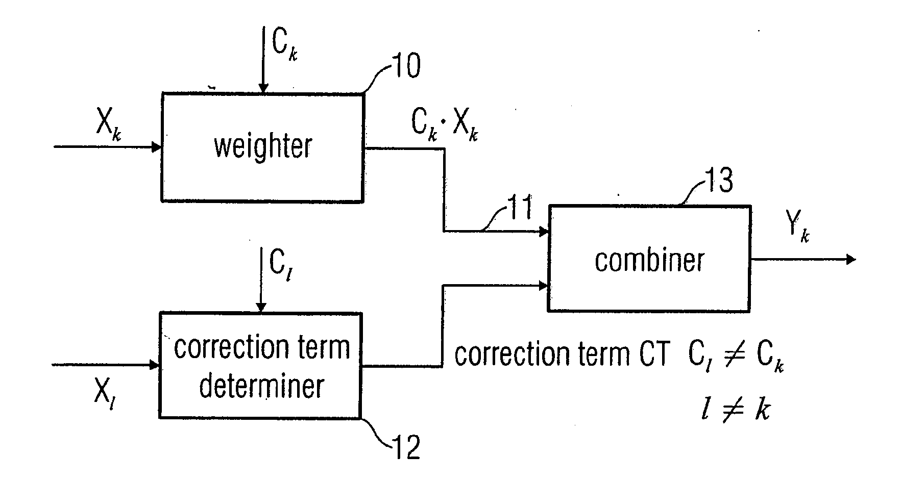
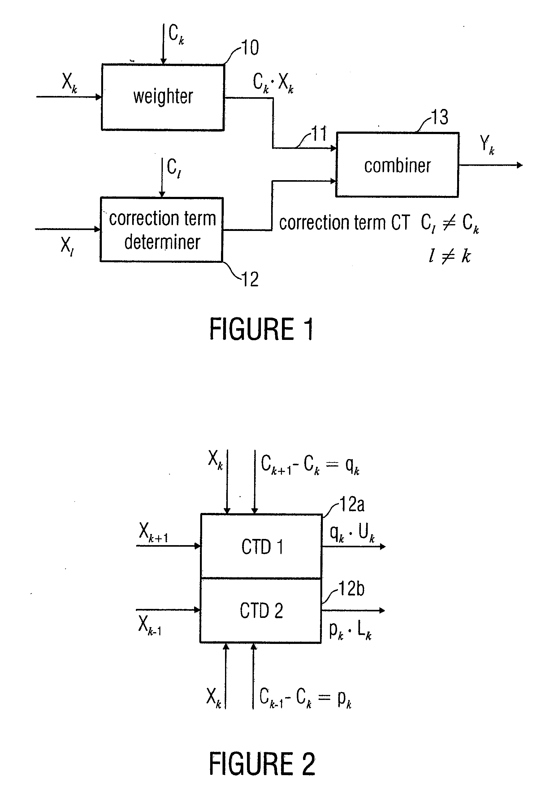
[0052]FIG. 1 shows an inventive device for processing a real subband signal x(k) of a plurality of real subband signals which are an illustration of a real discrete-time signal x(n) generated by an analysis filter bank (50 in FIG. 5). The inventive device includes a weighter 10 for weighting the subband signal xk by a weighting factor ck determined for the subband signal to obtain a weighted subband signal 11. The weighter is advantageously implemented to perform a multiplication. In particular, subband samples which are samples of a bandpass signal or spectral coefficients of a transform spectrum are multiplied by the correction factor. Alternatively, instead of multiplication, addition of logarithm values may also be performed, namely an addition of the logarithm of the correction value and the logarithm of the subband sample xk.

[0053]The inventive device for processing further includes a correction term determiner for calculating a correction term, the correction term determiner ...


PUM


Abstract

In order to process a subband signal of a plurality of real subband signals which are a representation of a real discrete-time signal generated by an analysis filter bank, a weighter for weighting a subband signal by a weighting factor determined for the subband signal is provided to obtain a weighted subband signal. In addition, a correction term is calculated by a correction term determiner, the correction term determiner being implemented to calculate the correction term using at least one other subband signal and using another weighting factor provided for the other subband signal, the two weighting factors differing. The correction term is then combined with the weighted subband signal to obtain a corrected subband signal, resulting in reduced aliasing, even if subband signals are weighted to a different extent.

Description

[0001]The present invention relates to processing audio or video signals and, in particular, to filter banks for converting a signal to a spectral representation, the spectral representation comprising bandpass signals or spectral coefficients.BACKGROUND OF THE INVENTION[0002]In applications in consumer and communication electronics, the possibility of manipulating the signal spectra by frequency-selectively increasing or decreasing signal intensities is desirable, such as, for example, for equalizer functionalities or echo suppression. In connection with audio coding methods which are based on spectrally decomposing the input signal, it seems to be obvious to correspondingly amplify and / or attenuate the decoded spectral components (subband samples and / or transform coefficients) by means of multiplication by amplification factors which may be temporally alterable. The filter banks used here, however, usually have real values and involve critical sampling. Consequently, the subband s...

Claims


Application Information

Patent Timeline
Patent Type & Authority Applications(United States)
IPC IPC(8): H04N11/02G10L19/02
CPCG10L19/0204H03G3/00H03H2218/04H03H17/0266G10L19/02H03M7/30
Inventor EDLER, BERNDPOPP, HARALD
Owner FRAUNHOFER GESELLSCHAFT ZUR FOERDERUNG DER ANGEWANDTEN FORSCHUNG EV
Why Eureka
Try Eureka