Image Display Apparatus, Video Signal Processor, and Video Signal Processing Method

a technology of image display and video signal, which is applied in the direction of signal generators with optical-mechanical scanning, instruments, television systems, etc., can solve the problems of weakening the degree of reduction of judder, losing film signal taste, and user discomfort, so as to reduce hold blur, improve picture quality, and improve picture quality

Active Publication Date: 2010-01-21
SATURN LICENSING LLC
View PDF14 Cites 24 Cited by
  • Summary
  • Abstract
  • Description
  • Claims
  • Application Information

AI Technical Summary

Benefits of technology

[0021]The present invention has been achieved in view of such issues, and its first object is to provide an image display apparatus, a video signal processor, and a video signal processing method capable of weakening the degree of reduction of a judder while reducing the judder at the time of converting frame rate of a film signal (cinema signal) using motion compensation.
[0028]In the image display apparatus, the video signal processor, and the video signal processing method of the invention, the video signal process is performed so that a degree of the video signal process rises as reliability in detection of a motion vector increases and, on the other hand, a degree of the video signal process falls off as the reliability decreases. Accordingly, in the case of performing a predetermined video signal process to improve picture quality by using the motion vector, a video signal process according to motion vector detection precision can be performed. Therefore, at the time of performing the predetermined video signal process to improve the picture quality, deterioration in picture quality according to the motion vector detection precision can be suppressed.

Problems solved by technology

As a result, a person accustomed to a judder in a film signal gets an impression that the taste of the film signal is lost.
In such a case, there is a problem that since a large judder suddenly occurs while the user is watching a video image in which motion is very smooth, the user feels discomfort.
However, a technique of weakening the degree of reduction of a judder while reducing the judder at the time of converting the frame rate of a film signal is not proposed.

Method used


Image

  • Image Display Apparatus, Video Signal Processor, and Video Signal Processing Method
  • Image Display Apparatus, Video Signal Processor, and Video Signal Processing Method
  • Image Display Apparatus, Video Signal Processor, and Video Signal Processing Method

Examples


first embodiment

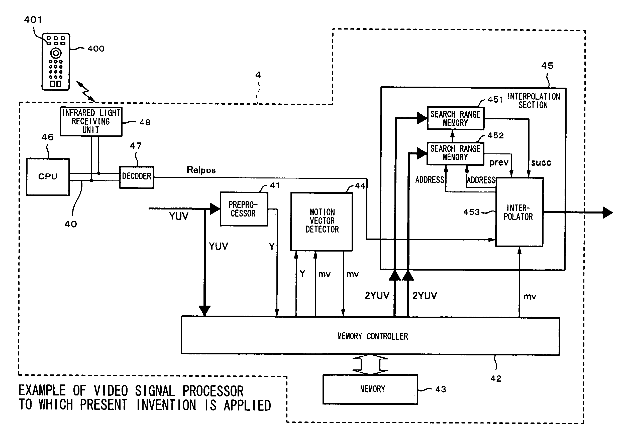
[0088]FIG. 5 is a block diagram showing an example of the circuit configuration of a video signal processor (video signal processor 4) according to a first embodiment of the present invention. The video signal processor 4 is built in a television receiver. A digital component signal YUV subjected to processes such as tuning and decoding by a tuner, a decoder, and the like which are not shown is supplied to the video signal processor 4.

[0089]The digital component signal YUV supplied to the video signal processor 4 is input to a preprocessor 41 and sequentially written to a memory 43 via a memory controller 42.

[0090]The preprocessor 41 performs a process of separating a luminance signal Y from the digital component signal YUV. The luminance signal Y separated by the preprocessor 41 is also sequentially written in the memory 43 via the memory controller 42.

[0091]The luminance signal Y written in the memory 43 is sequentially read by the memory controller 42 (as shown in FIGS. 2 and 3, ...

second embodiment

[0151]A second embodiment of the present invention will now be described.

[0152]FIG. 13 shows an example of the configuration of a video signal processor (video signal processor 4B) of the second embodiment. The same reference numerals are designated to the same components as those of the foregoing embodiment, and their description will not be repeated.

[0153]The video signal processor 4B executes various image processes on moving image data on an access unit basis. The access unit is a unit of a moving image such as a frame or a field and, concretely, refers to, for example, an entire picture or a part of a picture constituting a moving image. In this case, the picture denotes here a single stationary image. Therefore, the entire picture corresponds to a frame. However, hereinafter, for simplicity of explanation, it is assumed that the video signal processor 4B executes various image processes on moving image data on the frame unit basis.

[0154]As shown in FIG. 13, the video signal pr...

third embodiment

[0422]A third embodiment of the present invention will now be described.

[0423]FIG. 43 shows an example of the configuration of a video signal processor (video signal processor 4D) according to the embodiment. In addition, the same reference numerals are designated to the same components as those in the foregoing embodiments and their description will not be repeated.

[0424]The video signal processor 4D is obtained by further providing the video signal processor 4B described in the second embodiment with an overdrive processor 10 and performs video signal processes in the interpolation section 45, the imaging blur suppression processor 13, and the overdrive processor 10 in consideration of the reliability in detection of a motion vector mv in the motion vector detector 44. In addition, in the case of detecting a motion vector also in the imaging blur characteristic detector 12, reliability in detection of the motion vector may be considered. In the embodiment, the case where the imagi...


PUM

PropertyMeasurementUnit
degree of reductionaaaaaaaaaa
frequencyaaaaaaaaaa
shutter speedaaaaaaaaaa

Abstract

The present invention provides an image display apparatus capable of suppressing deterioration in picture quality resulting from precision of detection of a motion vector at the time of performing a predetermined video signal process to improve picture quality. In consideration of reliability in detection of a motion vector mv by a motion vector detector 44, a video signal process in an interpolation section 45, an imaging blur suppression processor 13, and an overdrive processor 10 is performed. Concretely, the video signal process is performed so that a degree of the video signal process rises as reliability increases and, on the other hand, a degree of the video signal process falls off as the reliability decreases. In the case of performing the video signal process using a motion vector, even when a motion vector lies out of a motion vector search range (block matching range), the video signal process according to the motion vector detection precision can be performed.

Description

TECHNICAL FIELD[0001]The present invention relates to a video signal processor and a video signal processing method for performing a predetermined video signal processing using motion compensation and to an image display apparatus having such a video signal processor.BACKGROUND ART[0002]As one of video signal processes for improving picture quality in a television receiver, a DVD player, and the like there is frame rate conversion using motion compensation.[0003]The principle of frame rate conversion will be described using FIGS. 1 to 3 with respect to a video signal captured by a camera for television broadcast (hereinbelow, referred to as a camera signal) and a video signal obtained by telecine converting a film to a television system (hereinbelow, called film signal or cinema signal).[0004]FIG. 1(a) shows original frames A, B, C, and D of a camera signal of an NTSC system. In the case of converting the frame rate of the camera signal to 120 Hz, as shown in FIG. 1(b), an interpola...

Claims


Application Information

Patent Timeline
Patent Type & Authority Applications(United States)
IPC IPC(8): H04N7/01H04N5/66G02F1/133G09G3/20G09G3/34G09G3/36H04N5/44
CPCG09G3/3406H04N7/0132G09G2310/024G09G2310/061G09G2320/0261G09G2320/0606G09G2320/062G09G2320/0626G09G2320/106G09G2340/0435G09G2360/144G09G2360/16H04N5/145H04N7/0112H04N7/012G09G3/3648G09G3/36H04N5/208H04N5/66
Inventor MIYAZAKI, SHINICHIROMURAKAMI, ICHIRONISHI, TORU
Owner SATURN LICENSING LLC
Why Eureka
Try Eureka