
LED backlight having edge illuminator for flat panel LCD displays

a flat panel lcd display and led backlight technology, applied in the direction of illuminated signs, display means, instruments, etc., can solve the problems of increased cost of led backlight units, difficult for led-based backlight units to compete with conventional low-cost ccfl backlighting systems, and hot spots of individual leds on the screen. , to achieve the effect of reducing depth, wide color gamut and superior color displays

Inactive Publication Date: 2010-01-21
JABIL CIRCUIT INC
View PDF4 Cites 50 Cited by
  • Summary
  • Abstract
  • Description
  • Claims
  • Application Information

AI Technical Summary

Benefits of technology

[0006]Compared to direct backlighting, an edge-lit arrangement has advantages such as reducing the depth and making the backlight unit thinner by placing LEDs along the sides and using very thin light guides to uniformly distribute light across the LCD panel. While it is easy to implement LEDs which emit white light in a backlighting system, red, green and blue (RGB) LEDs can provide a much wider color gamut and result in superior color displays. In an edge-lit based backlight unit, light rays from small RGB LED light sources are first coupled into light guides and then the light guides carry light internally. The light guide may also be referred to as a guide or a light guide plate. The guide has input surfaces from which light is coupled into the light guide.
[0007]Simple and thin light guide architectures with fewer LEDs can greatly reduce the cost of LED backlight units and promotes adoption of this technique into the mainstream in flat panel LCD displays. Light from the LED light sources can be coupled into a rectangular light guide from both lateral sides of the guide. A transition region known as the color mixing distance is provided between the LEDs and the illumination region of the guide. When the transverse dimension of the rectangular light guide is small, the associated color mixing distance is very short and color light from the individual RGB LEDs can be mixed very well before the light is extracted out from the guide. It is desirable that the color mixing distance be kept short so that the size of the bezel surrounding the flat panel LCD display can be kept small.
[0008]The backlight illumination is provided by a light guide plate. The light guide plates used in the backlighting units are made from a substantially transparent bulk plastic material. An example of a bulk material used in injection-molded light guides is acrylic (PMMA) for low cost, lightweight, and less light absorption. The light guide plate will further include micro-structures (i.e., micro-lenses) on the top and bottom surfaces to extract light out from the light guide for illuminating the viewing area of the LCD display. Because the micro-lenses can be made very small and dense, uniform light distribution can be achieved on large LCD screens even the backlight units are very slim.
[0009]One or more embodiments of the present invention are able to achieve good brightness and good color uniformity by use of light-reshaping structures that produce a well-mixed and color-balanced distribution of light. The light-reshaping structures allow the design to use fewer LEDs, and fewer electrical components, thereby producing a design that is low-cost, thin and simple.

Problems solved by technology

A drawback of direct backlighting is that hot spots from individual LEDs may be visible on the screen unless either the LED array is dense, or the backlight unit is deep.
The use of such a huge number of LEDs results in complex control systems and significantly increases the cost of LED backlight units, making it difficult for LED-based backlight units to compete with conventional low-cost CCFL backlighting systems.

Method used


Image

  • LED backlight having edge illuminator for flat panel LCD displays
  • LED backlight having edge illuminator for flat panel LCD displays
  • LED backlight having edge illuminator for flat panel LCD displays

Examples


Embodiment Construction

[0019]One or more embodiments of the present invention includes an elongated light guide apparatus adapted to accept light from two RGB LED chipsets, one on each end of the light guide, in order to produce highly uniform light that has a highly uniform color distribution and highly uniform intensity distribution. The highly uniform light is produced with high efficiency and at low cost by use of structures as described below.

[0020]One or more embodiments of the present invention includes a light guide plate adapted to accept light from the edge lighting apparatus, in order to produce backlight illumination for an LCD display.

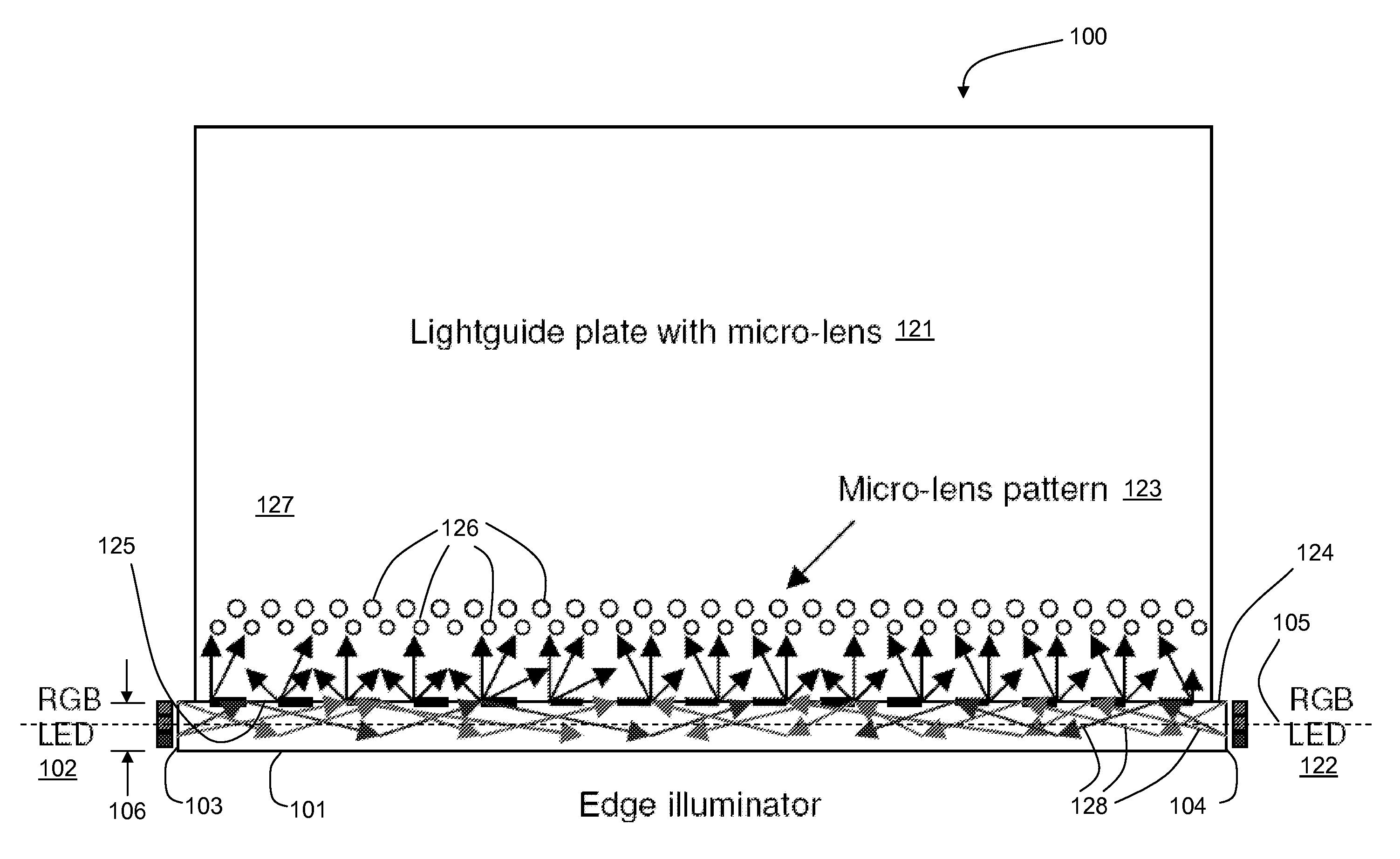
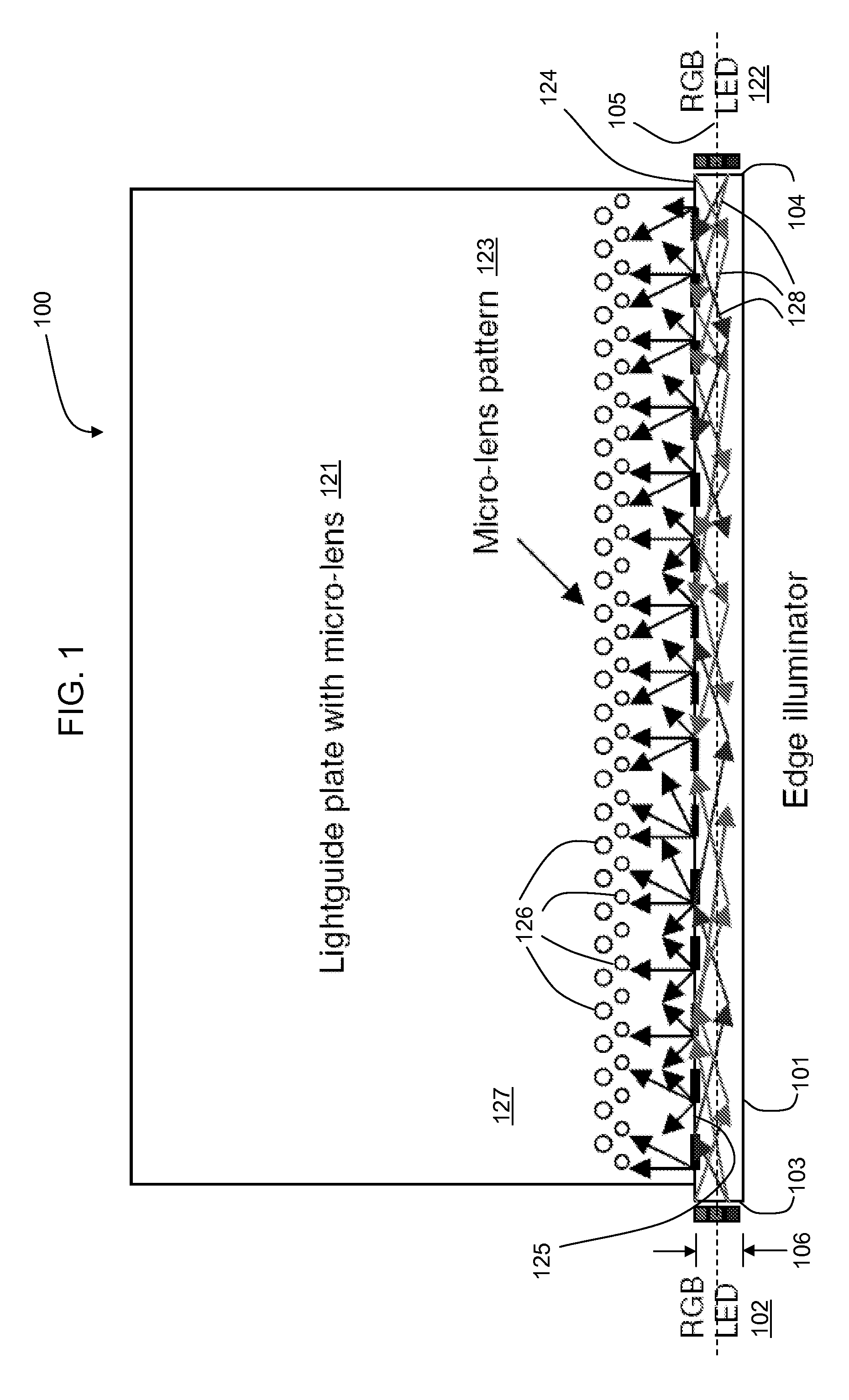
[0021]FIG. 1 shows an exemplary front view of an embodiment of the present invention, wherein the light guide is positioned to inject light into the bottom edge of a light guide plate.

[0022]FIG. 1 shows a front view of a first exemplary LED backlight unit 100, constructed from a light guide 101 and a light guide plate 121. Both light guide and light guide plate ...


PUM


Abstract

One or more embodiments of the present invention provide apparatuses and systems to form edge-illuminated LED backlight units for flat-panel LCD displays. The backlight unit is able to achieve uniform color and brightness distribution with very small dimensions of depth and bezels. One or more embodiments of the present invention include a light guide coupled to a light guide plate, which, by operating together, provide simple, efficient, few LEDs and low cost backlight units. Effective coupling structures provide high system efficiency.

Description

CROSS REFERENCE TO RELATED APPLICATIONS [0001]This non-provisional U.S. Patent Application claims the benefit of U.S. Provisional Patent Application No. 61 / 081,287 entitled “LED BACKLIGHT HAVING EDGE ILLUMINATOR FOR FLAT PANEL LCD DISPLAYS” filed on Jul. 16, 2008, the disclosure of which is incorporated herein by reference.BACKGROUND OF THE INVENTION[0002]1. Statement of the Technical Field[0003]This invention pertains to innovative LED-based backlight units used for flat panel LCD displays, in particular pertaining to light guide architectures having low cost, high efficiency, few LEDs, and uniform light distribution across a display screen.[0004]2. Description of the Related Art[0005]Light emitting diodes (LEDs) are gradually extending their applications in LCD backlight units from small panels to large screen LCD displays. One typical approach, known as direct backlighting, disposes an array of LEDs directly on the back surface of a backlight unit. A drawback of direct backlighti...

Claims


Application Information

Patent Timeline
IPC IPC(8): G02F1/13357
CPCG02B6/0028G02B6/0036G02F1/133615G02B6/0068G02B6/0073G02B6/0046
Inventor LI, LINMOREJON, ISRAEL J.
Owner JABIL CIRCUIT INC
Learn More