Means of eliminating electrolytic capacitor as the energy storage component in the single phase ad/dc two-stage converter

a technology of ad/dc two-stage converter and ad/dc, which is applied in the field of power factor correction circuit, can solve the problems of limited lifetime and higher cost of conventional pfc circuit, and achieve the effect of prolonging the lifetime of pfc circui

Active Publication Date: 2010-01-21
SPI ELECTRONICS +1
View PDF3 Cites 55 Cited by
  • Summary
  • Abstract
  • Description
  • Claims
  • Application Information

AI Technical Summary

Benefits of technology

[0003]In view of the problem of the conventional power factor correction (PFC) converter that is limited by the lifetime of electrolytic capacitor, it is an object of the present invention to provide a circuit structure to overcome the aforesaid shortcoming of the conventional techniques and prolong the lifetime of PFC circuit.

Problems solved by technology

So the conventional PFC circuit 1 has a limited lifetime due to the usage of electrolytic capacitor.
Therefore, incorporating the PFC circuit 1 in a long life electronic element results in a waste.
This is a waste and makes the cost higher.

Method used


Image

  • Means of eliminating electrolytic capacitor as the energy storage component in the single phase ad/dc two-stage converter
  • Means of eliminating electrolytic capacitor as the energy storage component in the single phase ad/dc two-stage converter
  • Means of eliminating electrolytic capacitor as the energy storage component in the single phase ad/dc two-stage converter

Examples


Embodiment Construction

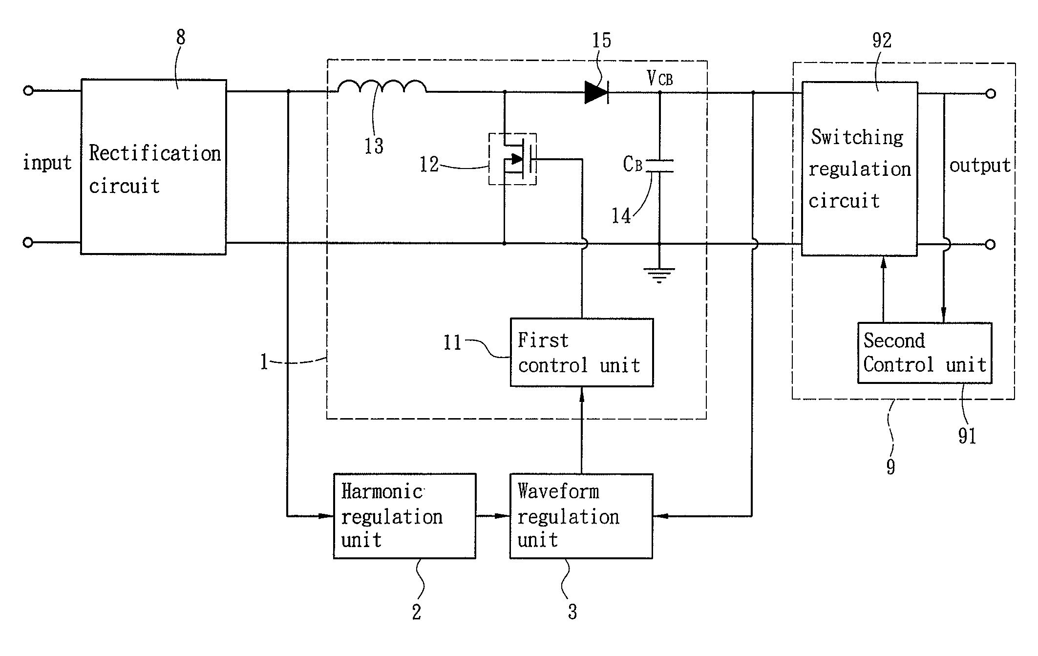
[0020]Please refer to FIG. 4 for a circuit block diagram of an embodiment of the invention. The power supply according to the invention includes a rectification unit 8, a power factor correction (PFC) circuit 1 and a power conversion unit 9. The power conversion unit 9 may be a flyback circuit. The PFC circuit 1 includes an inductor 13, a storage capacitor 14, a switch 12, a diode 15 and a first control unit 11. The first control unit 11 generates a period control signal to drive switching of the switch 12, thereby controls an inductor current passing through the inductor 13 so that the input power factor is regulated. The PFC circuit 1 is driven by the first control unit 11, and the power conversion unit 9 is driven by a second control unit 91. The PFC circuit 1 is set on by a switch 12 switched by the first control unit 11 to regulate input power factor. This is a technique known in the art, thus details are omitted herein. In FIG. 4 when the input power factor is unity, the input...


PUM


Abstract

A power factor correction (PFC) circuit includes an inductor, a diode, a storage capacitor, a switch and a control unit. The input power has a voltage fluctuation V1. The storage component absorbs a first voltage fluctuation and a switch regulation circuit absorbs a second voltage fluctuation V2. Thus output voltage from the PFC circuit is not a conventional constant voltage but a voltage of a great ripple. The PFC circuit further has a harmonic regulation unit. The harmonic regulation unit generates a voltage signal containing 3rd harmonic. The control unit receives a feedback signal and the voltage signal containing 3rd harmonic to generate a reference to the inductor current. Therefore, the inductor current contains 3rd harmonic. Thus power fluctuation absorbed and released by the capacitor is smaller. As a result energy storage capacitance can be reduced significantly.

Description

FIELDS OF THE INVENTION[0001]The present invention relates to a power factor correction circuit and particularly to a control circuit for using in active power factor correction circuit.BACKGROUNDS OF THE INVENTION[0002]Power supply is widely used in various types of electronic devices nowadays. As technology advances constantly, the output power of power supply also increases continuously. To further boost the output power, its power efficiency has to be enhanced. There are many factors impacting efficiency, such as the input power factor and loss of power conversion. Power factor correction (PFC in short hereinafter) converter is used to improve the input power factor in the power supply. An active PFC circuit can improve the power factor to 95% or more. Referring to FIG. 1, the input power goes through a rectification circuit 8 and is regulated by the PFC circuit 1 to correct the input power factor. Then the output voltage of the PFC circuit 1 is further regulated by a Power conv...

Claims


Application Information

Patent Timeline
Patent Type & Authority Applications(United States)
IPC IPC(8): H02M1/14
CPCH02M1/14Y02B70/126H02M1/4225Y02B70/10Y02P80/10
Inventor GU, LINLINXU, MINGRUAN, XINBOYAO, KAI
Owner SPI ELECTRONICS
Why Eureka
Try Eureka