Packet distribution system and packet distribution method

a packet distribution and packet technology, applied in the field of packet distribution technique, can solve the problems of data copy becoming burdensome, data copy requiring a lot of hardware resources, and unnegligent load on the system at the time of the copying process, and achieve the effect of suppressing system load

Active Publication Date: 2010-01-21
NEC CORP
View PDF15 Cites 10 Cited by
  • Summary
  • Abstract
  • Description
  • Claims
  • Application Information

AI Technical Summary

Benefits of technology

[0025]Making a configuration as mentioned above makes it possible to distribute a data to a plurality of the peripheral terminals with a load upon the distribution-side network system suppressed to a level as low as possible at the moment of switching the session realized between the mobile terminal and the network side to the session using a plurality of the peripheral terminals together having respective functions.
[0026]The reason is that there is no necessity for analyzing the content of the packet in the distribution side, and only transmission of the packet to the communication device constituting the present invention enables the packet to be distributed to the remaining relay destination peripheral terminals after going through a header process by the header processing

Problems solved by technology

By the way, while such technologies have been proposed, some issues at point exist therein.
Further, the above technology necessitate performing a data copy in an Internet side/a network-side network at the moment of distributing the streaming data etc. to a plurality of the peripheral terminals, and the data copy becomes burdensome as an amount of the data is increased.
That is, the data copy demands a lot of hardware resources such as a hard disc, and a load upon a system at the time of the copying

Method used


Image

  • Packet distribution system and packet distribution method
  • Packet distribution system and packet distribution method
  • Packet distribution system and packet distribution method

Examples


first embodiment

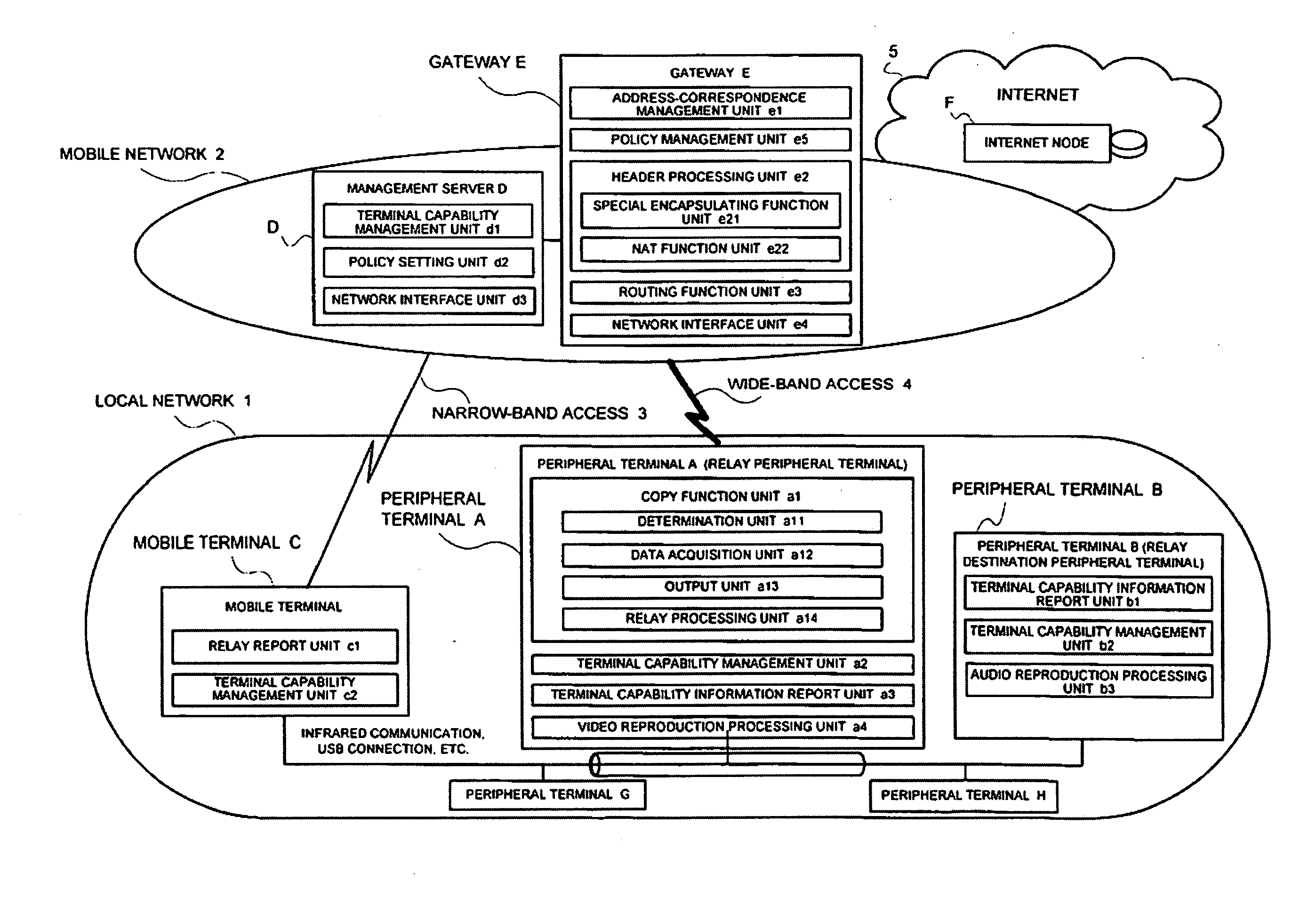
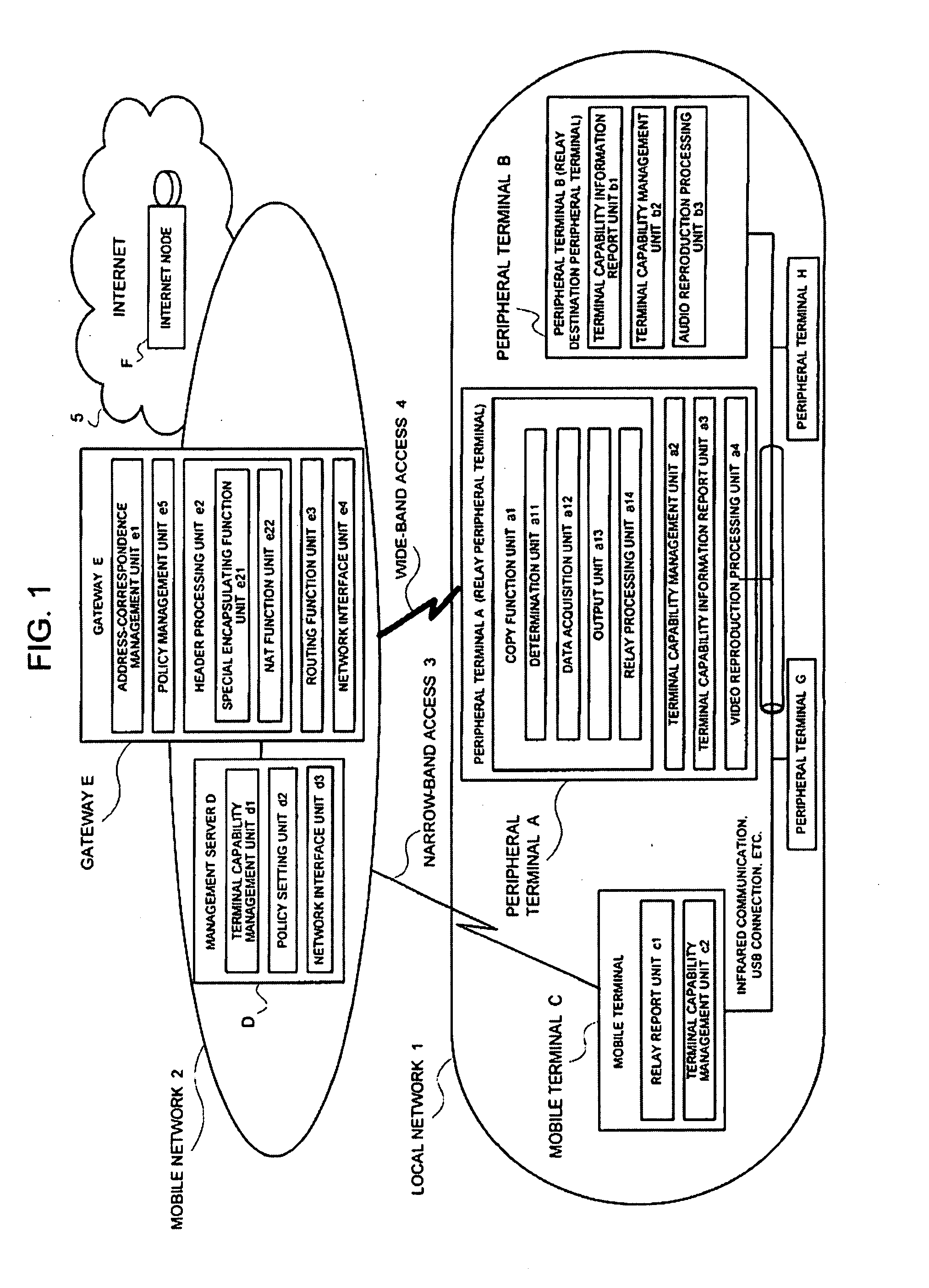
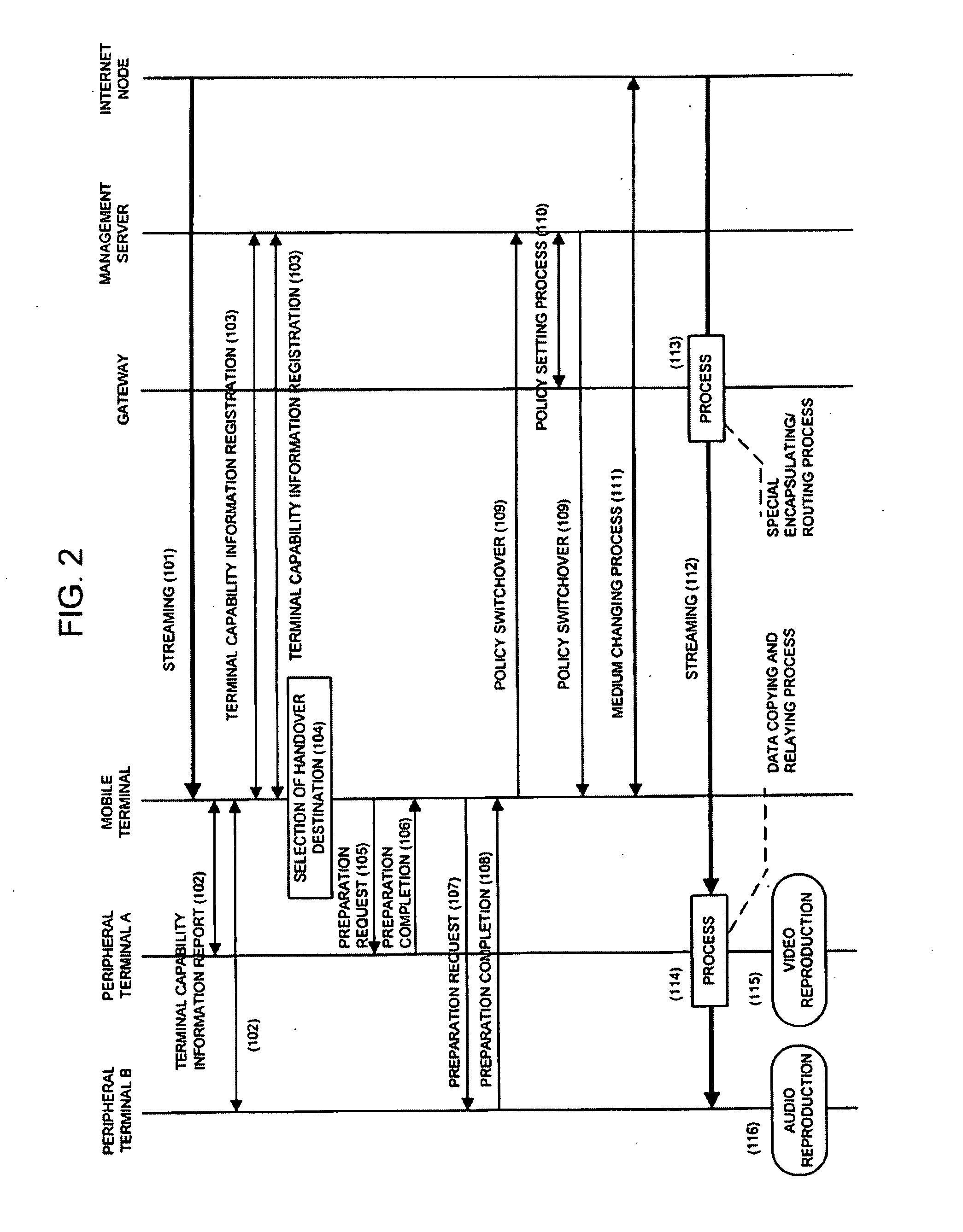
[0066]Each of FIG. 1 to FIG. 4 is for explaining the packet distribution system of the present invention, FIG. 1 is a block diagram of the packet distribution system, FIG. 2 is a sequence diagram of a process, and each of FIG. 3 and FIG. 4 is an explanatory view illustrating a packet configuration at the time of processing a header.

[0067]Upon making a reference to FIG. 1, C, which is a mobile terminal, is a terminal having subscribed for a service of a mobile network 2. An independent network is constructed among the mobile terminal C and the peripheral terminals. That is, the mobile terminal C is local-connected by a local network 1. What is herein called the local connection includes, for example, infrared-ray communication, and a connection technique such as a USB connection. In addition hereto, the mobile terminal C is connected to the mobile network 2, being an external network, via a narrow-band access 3. The narrow-band access 3 is a communication link of which a communicatio...

second embodiment

[0135]Next, the second embodiment will be explained by employing FIG. 2, FIG. 4, and FIG. 5.

[0136]Each of FIG. 2, FIG. 4, and FIG. 5 is for explaining the second embodiment of the packet distribution system of the present invention, FIG. 5 is a block diagram of the entirety, FIG. 2 is a sequence diagram illustrating a processing flow of the packet, and FIG. 4 is a view illustrating a configuration example of the packet.

[0137]Additionally, each unit constituting the second embodiment is identical to that of the first embodiment except for a copy function unit a5 / a header processing unit e6, so the identical configuration part will be explained by employing numeral codes identical to the numeral codes used in the explanation of the first embodiment.

[0138]Upon making a reference to FIG. 5, a configuration in the second embodiment of the present invention includes the header processing unit e6 and the copy function unit a5 in addition to the components of the first embodiment.

[0139]The ...


PUM


Abstract

Provided is a technique for switching a session between a terminal and a network to a session using a plurality of peripheral terminals having respective functions, by considering the load on the distribution side system and distributing a packet to the plurality of peripheral terminals. This application for relaying a packet transmitted from a distribution node via a communication device in response to a request from a terminal to a relay destination peripheral terminal that becomes a relay destination, characterized in comprising: data acquiring means for decapsulating the packet encapsulated by the communication device, thereby to acquire a payload data; outputting means for outputting the acquired data by the data acquiring means to a predetermined reproduction function; and relay processing means for, based upon header information being contained in the decapsulated packet, relaying the decapsulated packet to the relay destination peripheral terminal.

Description

APPLICABLE FIELD IN THE INDUSTRY [0001]The present invention relates to a distribution technique of a packet, and more particularly to a packet distribution technology of distributing a packet transmitted from a distribution node in response to a request from a terminal to a plurality of terminals.BACKGROUND ART [0002]Use of a mobile telephone as an Internet terminal has drastically progressed, and services as well utilizing the mobile telephone have been diversified. The recent mobile telephone, which utilizes infrared-ray communication or USB, is connectable to other peripheral terminals, and utilization thereof as a mobile terminal has been generalized. Further, the mobile telephone is inclined to increasingly process a large capacity of data.[0003]Under such a situation, a technology of shifting a session in communication from a narrow-band mobile terminal to a terminal having a wide-band interface provided therein has already been generalized.[0004]For example, there exists the...

Claims


Application Information

Patent Timeline
IPC IPC(8): H04J3/08H04L45/741
CPCH04L67/2814H04L67/289H04L67/148H04L67/14H04L67/563
Inventor FUJINO, SHOZO
Owner NEC CORP
Why Eureka
Try Eureka