Airflow boosting assembly for a forced air circulation and delivery system

Inactive Publication Date: 2010-01-21
NORTH AMERICA RANGE HOODS
View PDF17 Cites 17 Cited by
  • Summary
  • Abstract
  • Description
  • Claims
  • Application Information

AI Technical Summary

Benefits of technology

[0010]In an embodiment, the booster fan includes a register plate for covering a vent opening. An opening or openings on the register plate provide an air outlet. A housing is secured to the register plate for enclosing a crossflow fan therein. The housing is dimensioned to be smaller than the vent opening for passing therethrough. The crossflow fan is disposed adjacent and spaced from the register plate and resiliently supported at both ends. A motor is resiliently connected to the crossflow fan in a driving relation. The housing also has an aperture for providing an air inlet communicating with the duct system. Preferably, two arcuate air deflection panels are provided in the housing and connecting the air inlet and air outlet to form a guided air passageway.
[0011]In a first aspect of the invention, there is provided an airflow boosting assembly for installation in a vent opening of a forced air circulation and delivery system. The airflow boosting assembly includes a register plate for covering the vent opening, the register plate having defined therein an air outlet; a housing, the housing having an air inlet spaced from the air outlet, the housing being dimensioned to be smaller than the vent opening for passing therethrough; a crossflow fan disposed between the air inlet and the air outlet, the crossflow fan having a rotational axis, the crossflow fan being oriented such that the rotational axis is generally parallel to the register plate; an elastomeric motor connector; a motor secured to the housing, the motor being connected to the crossflow fan in a driving relation through the elastomeric motor connector; an elastomeric bearing housing attached to the housing and a bearing resiliently housed in the bearing housing; the crossflow fan having a shaft rotationally supported in the bearing, the bearing housing biasing the crossflow fan toward the motor along a direction generally parallel to the rotational axis; and a control circuitry for selectively energizing the motor.
[0012]In a second aspect, there is provided an airflow boost

Problems solved by technology

Such a centralized air circulation and delivery system, however, does not always provide satisfactory results.
An air blower fan may not be sufficiently powerful to deliver the desired volume of air to such a bedroom, thereby may not be able to heat or cool the room to the desired temperature.
The duct system may not be always designed to compensate for the different lengths of duct paths to reach individual rooms, with the result of uneven distribution and delivery of air in individual rooms in a building.
This generally wastes energy.
This solution does not provide a satisfactory solution.
Dampers are generally located some distance away from vents or may be hidden behind floor or wall coverings and therefore difficult to reach.
Restricting or reducing air flow at some vents generally reduces the efficiency of the entire air delivery system.
The efficiency of the air circulation and delivery system tends to be reduced as a result.
More importantly, restricting air flow in s

Method used


Image

  • Airflow boosting assembly for a forced air circulation and delivery system
  • Airflow boosting assembly for a forced air circulation and delivery system
  • Airflow boosting assembly for a forced air circulation and delivery system

Examples


Embodiment Construction

[0034]The description which follows and the embodiments described therein are provided by way of illustration of an example, or examples, of particular embodiments of the principles of the present invention. These examples are provided for the purposes of explanation, and not limitation, of those principles and of the invention. In the description which follows, like parts are marked throughout the specification and the drawings with the same respective reference numerals.

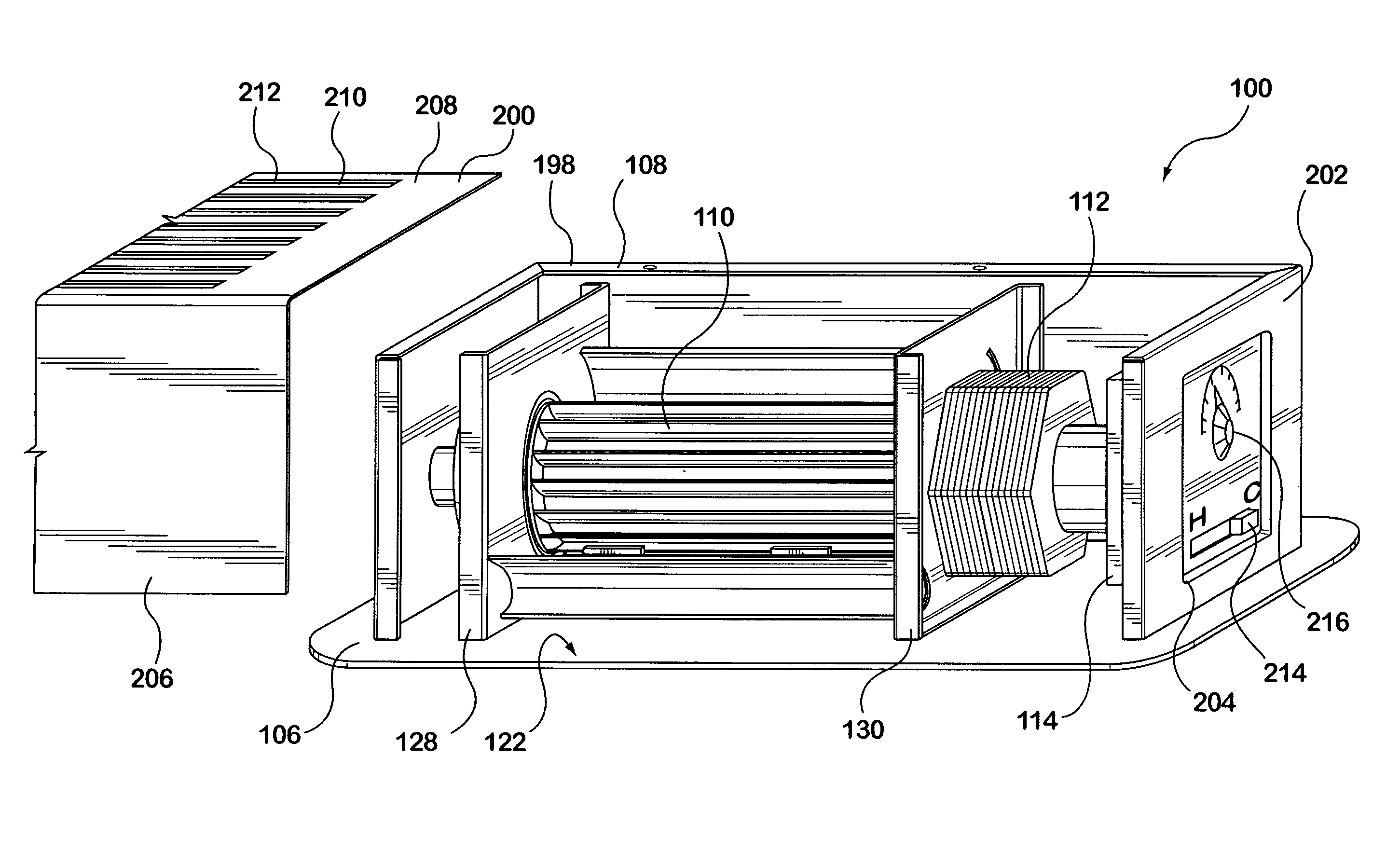
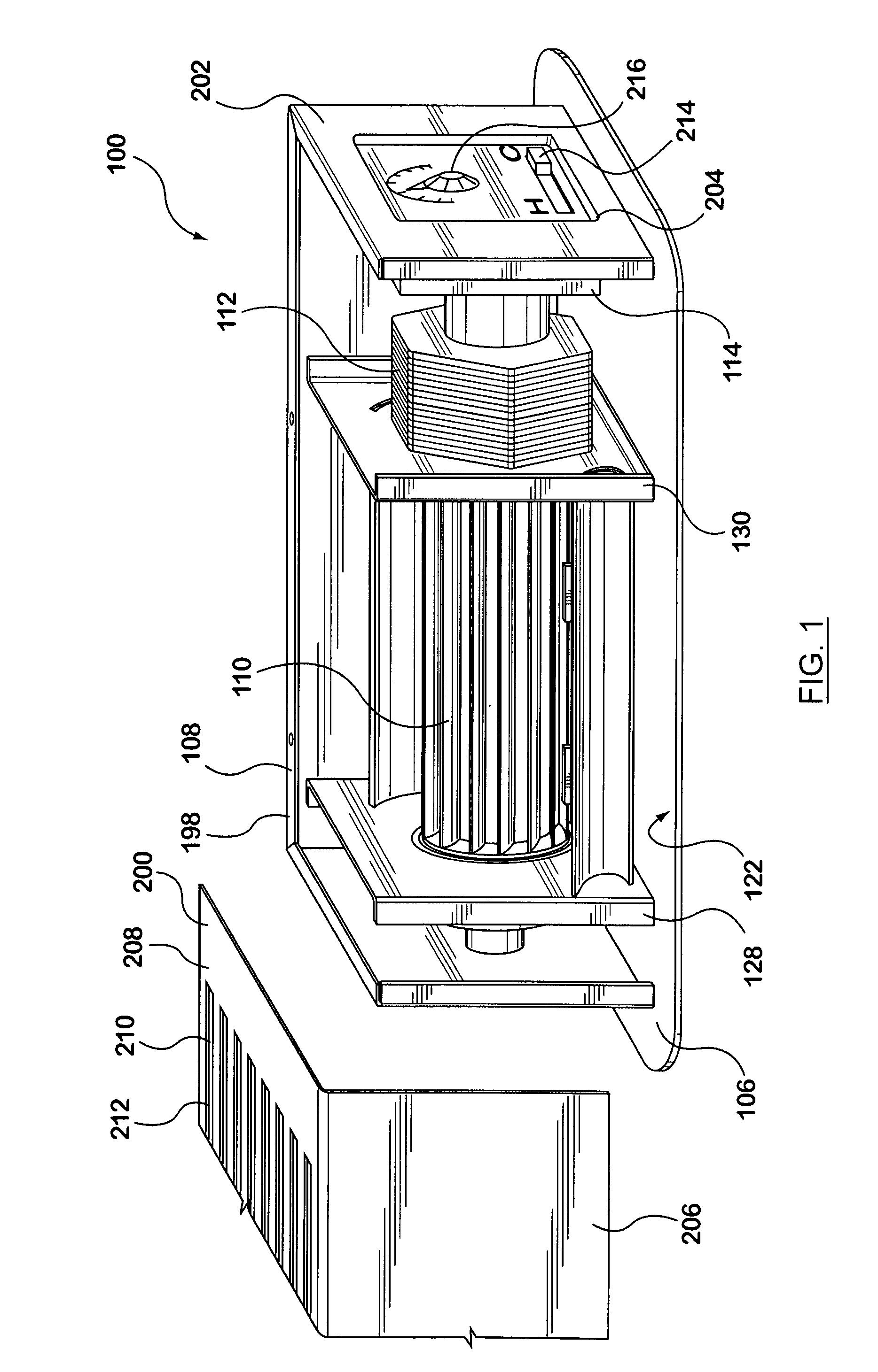
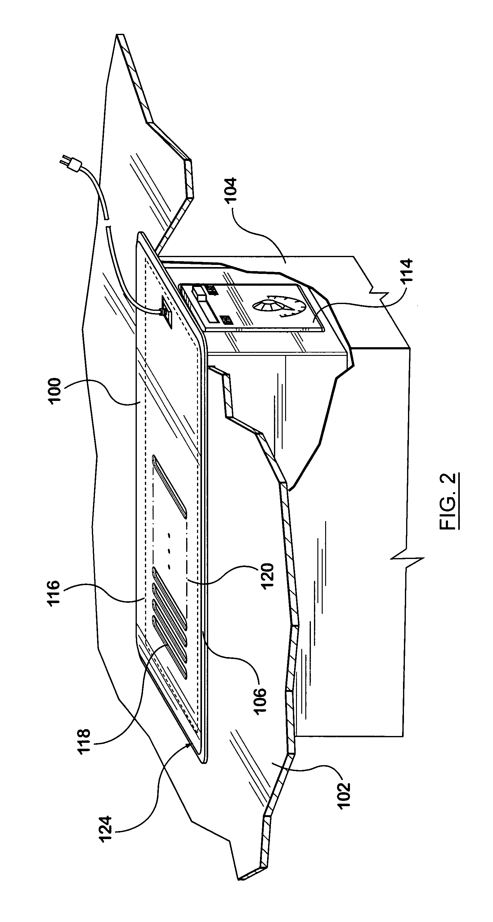
[0035]The invention relates generally to the field of airflow boosting devices. In particular, the invention relates to a booster fan for installation into a vent opening of a duct system in a forced air circulation and delivery system. Although a forced air circulation and delivery system typically installed in a residential building is referenced in the examples that follow, it will be appreciated that the invention is not restricted to such a system in a residential building. A booster fan according to the prese...


PUM


Abstract

The invention relates generally to the field of airflow boosting devices. In particular, the invention relates to a booster fan for installation into a vent opening of a duct system in a forced air circulation and delivery system. In an embodiment, the booster fan includes a register plate for covering a vent opening. An opening or openings on the register plate provide an air outlet. A housing is secured to the register plate for enclosing a crossflow fan therein. The crossflow fan is disposed adjacent and spaced from the register plate and resiliently supported at both ends. A motor is resiliently connected to the crossflow fan. The housing also has an aperture for providing an air inlet communicating with the duct system. Preferably, two arcuate air deflection panels are provided in the housing for connecting the air inlet and air outlet to form a guided air passageway.

Description

CROSS-REFERENCE TO RELATED APPLICATIONS[0001]This application is a continuation-in-part of application Ser. No. 11 / 686,692, which claims priority from Canadian Patent Application No. 2,581,241 for “Airflow Boosting Assembly for a Forced Air Circulation and Delivery System” filed on Mar. 7, 2007 which is hereby incorporated by reference.FIELD OF INVENTION[0002]The invention relates generally to the field of airflow boosting devices. In particular, the invention relates to a booster fan for installation into a vent opening of a duct system in a forced air circulation and delivery system.BACKGROUND OF INVENTION[0003]Modern residential buildings are often equipped with a central air circulation and delivery system, which utilizes an air blower fan to force air into individual rooms through an air delivery duct system in the buildings. When the circulated air is heated or cooled or otherwise conditioned, circulation of the air inside a building also provides heating or cooling of ambient...

Claims


Application Information

Patent Timeline
IPC IPC(8): F24F13/08F24F7/00F24F7/007
CPCF24F7/007F24F7/065F24F13/08F24F11/0012F24F13/082F24F11/30F24F2110/10F16D3/76F04D17/04F24F11/76
Inventor HU, SINE KON
Owner NORTH AMERICA RANGE HOODS
Why Eureka
Try Eureka