
Communication scheme for channel quality information

a communication scheme and channel quality technology, applied in the field of channel quality information communication scheme, can solve the problems of low accuracy of reconstructed resource block-wise channel quality information, inability to meet the requirements of a transmission system, and inability to offer optimal solutions for transmitting cqi information. dct-based schemes can solve the problem of low signalling overhead of index signals, and achieve the effect of reducing the overhead of index signalling

Active Publication Date: 2010-01-21
OPTIS WIRELESS TECH LLC
View PDF5 Cites 45 Cited by
  • Summary
  • Abstract
  • Description
  • Claims
  • Application Information

AI Technical Summary

Benefits of technology

The invention provides a solution for transmitting channel quality measures from a transmitter to a receiver in a communication system. The solution involves dividing the channel quality measures into distinct partitions, which helps to reduce the amount of overhead that needs to be attributed to the signalling of channel quality information. This allows for accurate reconstruction of the channel quality measures at the receiver and also allows for the efficient allocation of resources for data transmission. The receiver then uses the encoded channel quality measures to schedule air interface resources and determine link adaptation. The invention also suggests a method for reordering the channel quality measures prior to transmission to improve the accuracy of the reconstructed channel quality measures. Overall, the invention provides a more efficient and accurate way to transmit channel quality information in a communication system.

Problems solved by technology

It requires the least amount of transmitted information, however it also offers a generally very low accuracy with respect to the reconstructed resource block-wise channel quality information.
This requirement may be too high to fulfil in a transmission system, particularly in cellular mobile radio systems where a large number of entities have to report CQI values.
Also DCT-based schemes do not offer an optimal solution for transmitting the CQI information.
Since only a limited number of coefficients is transmitted in a DCT compression scheme, the reconstruction at the receiver (which typically offers scheduling functions) is generally not optimum for any resource block.
Consequently there will be deviations for the strongest resource blocks, which will result in erroneous scheduler decisions or suboptimum adaptive modulation and coding decisions by the link adaptation entity.
Particularly in case that M is rather small, a problem occurs if a user is assigned more resource blocks than M resource blocks.
Furthermore, a subsequent link adaptation would also be based on such an average value, resulting in suboptimum link adaptation and consequently in reduced spectral efficiency.
This problem may be circumvented by a high number M, however at the drawback that a lot of feedback signalling is required in this case.
Therefore another potential problem is to suggest a coding scheme that requires a small amount of feedback signalling.
On the one hand, a small number of M will result in similar problems as a small M in the “Best M Individual” scheme.
Additionally, the accuracy of the best M resource blocks reported is not as high as in the “Best M Individual” scheme, further deteriorating the accuracy of scheduling or link adaptation performance.
On the other hand, a simple increase of M is not guaranteed to improve the behaviour of the “Best M Average” scheme.
Even though the number of resource blocks which are contained within the signalled set increases, the averaging over those M resources will decrease the accuracy for those resource blocks.
In any case, finding this value of M may not be trivial in a mobile or cellular environment, and—in addition—even when having found an appropriate M value, the achievable data transmission throughput in data transmission is generally bad because of the averaging feature of this scheme.
It should be obvious to those skilled in the art that the information conveyed by the average CQI scheme is of very low accuracy.

Method used


Image

  • Communication scheme for channel quality information
  • Communication scheme for channel quality information
  • Communication scheme for channel quality information

Examples


Embodiment Construction

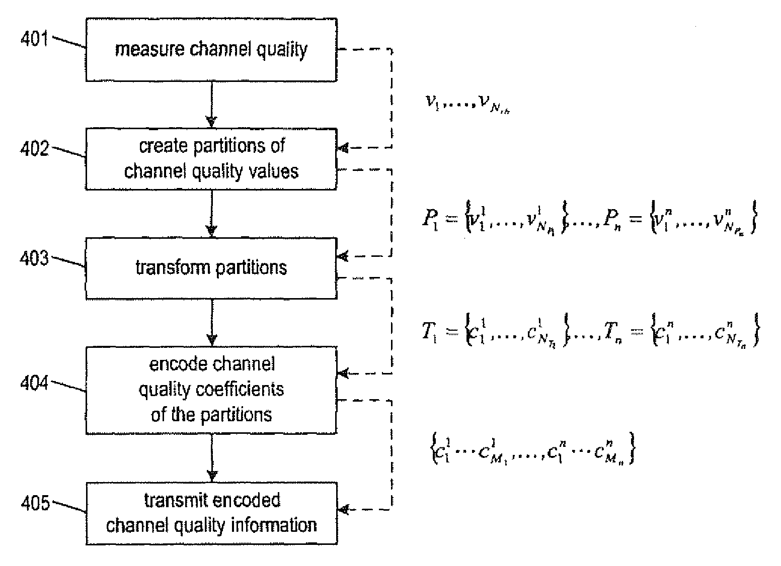
[0128]Before outlining the concepts and the ideas of the invention according to different embodiments in further detail, the following notation used herein should be recognized:[0129]Nrb denotes the total number of resource unit of a channel,[0130]vi or vij denotes a channel quality value i for resource unit i, where i=,K,NRB, j may indicate the partition Pj, to which the channel quality value has been assigned[0131]NPi denotes the number of channel quality values in partition Pi [0132]Pi={v1i,K, vNAi} denotes a set or partition having NPi channel quality values[0133]ci or cij denotes a channel quality coefficient i, j may indicate the transformed partition Tj of the channel quality coefficient[0134]NTi denotes the number of channel quality coefficients in a set or transformed partition Ti

Ti={c1i,K,cNTii}[0135]Ti={c1i,K,cNT} denotes a set or transformed partition having NTi channel quality coefficients obtained by transforming partition Pi [0136]Nr denoted the total number of define...


PUM


Abstract

The invention relates to a method for transmitting and a method for reconstructing channel quality information in a communication system. Further, the invention also provides a transmitter and receiver performing these methods, respectively. The invention suggests a scheme for communicating channel quality measures that on the one hand allows for an accurate reconstruction of the channel quality measures at the receiver and on the other hand requires an acceptable transmission overhead. This is achieved by partitioning channel quality measures into at least two partitions and to compress the values partition-wise, for example by means of a discrete cosine transform and the transmission of only a subset of the resulting coefficients.

Description

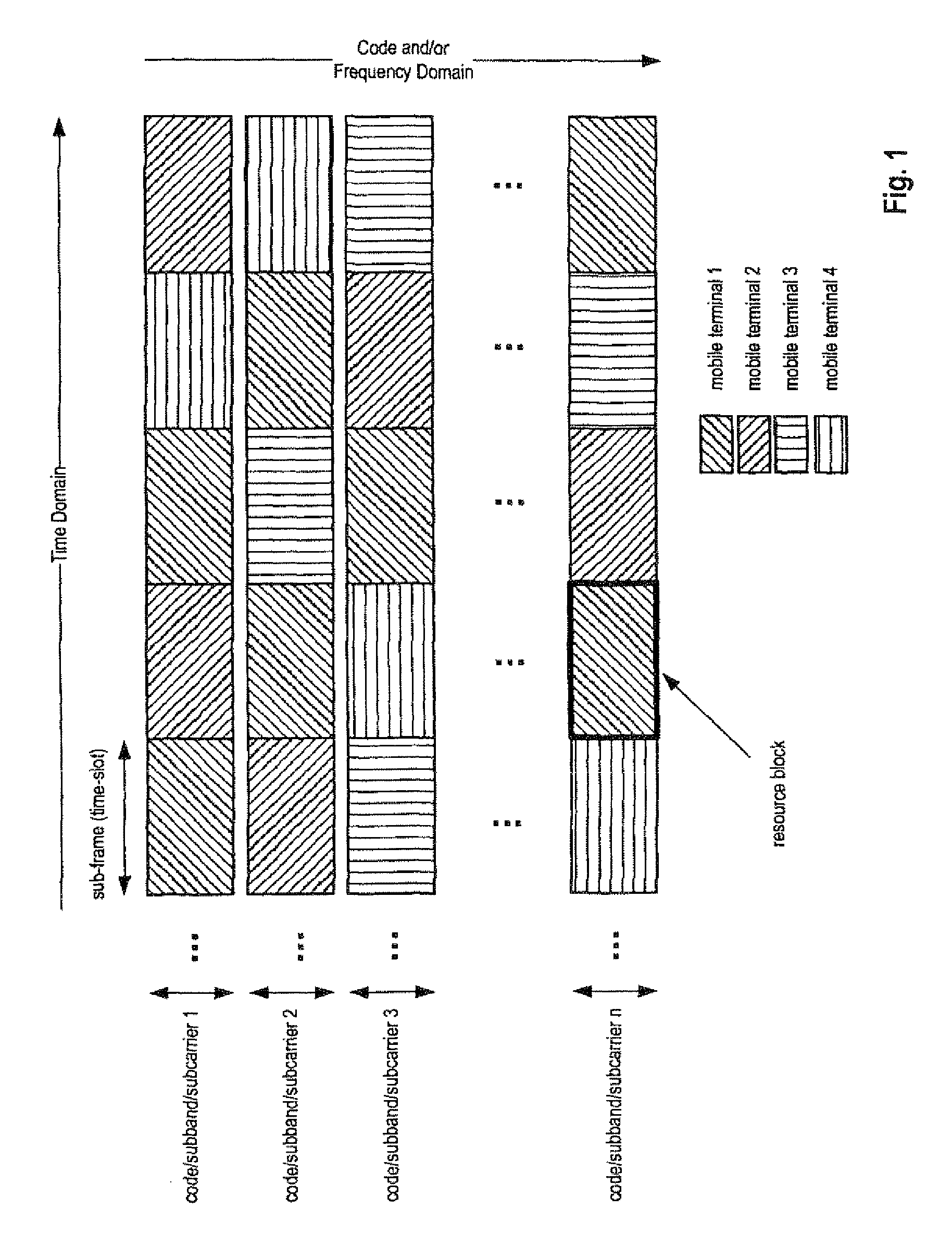
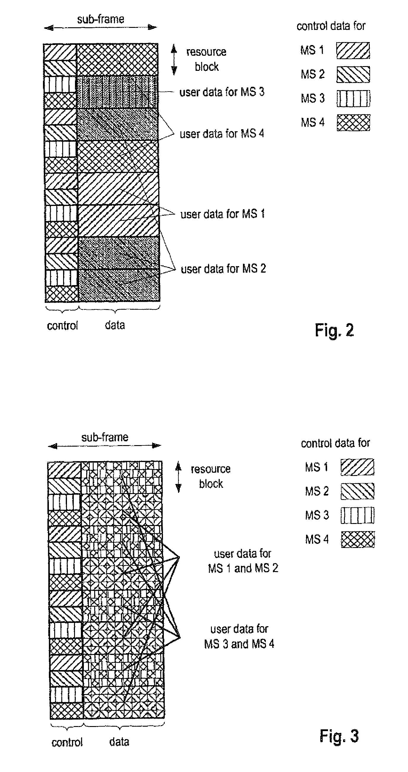
FIELD OF THE INVENTION[0001]The invention relates to a method for transmitting and a method for reconstructing channel quality information in a communication system. Further, the invention also provides a transmitter and receiver performing these methods, respectively.TECHNICAL BACKGROUNDPacket-Scheduling and Shared Channel Transmission[0002]In wireless communication systems employing packet-scheduling, at least part of the air-interface resources are assigned dynamically to different users (mobile stations—MS). Those dynamically allocated resources are typically mapped to at least one shared data channel (SDCH). A shared data channel may for example have one of the following configurations:[0003]One or multiple codes in a CDMA (Code Division Multiple Access) system are dynamically shared between multiple MS.[0004]One or multiple subcarriers (subbands) in an OFDMA (Orthogonal Frequency Division Multiple Access) system are dynamically shared between multiple MS.[0005]Combinations of ...

Claims


Application Information

Patent Timeline
Patent Type & Authority Applications(United States)
IPC IPC(8): H04B17/00
CPCH04L1/0026H04W24/10H04L1/0028H04L1/0027H04W72/0453H04B7/0413H04W84/042H04W88/02
Inventor GOLITSCHEK, ALEXANDER
Owner OPTIS WIRELESS TECH LLC
Learn More