Temperature and wear and tear sensor for brake or clutch devices

Active Publication Date: 2010-01-21
TMD FRICTION SERVICES
View PDF15 Cites 9 Cited by
  • Summary
  • Abstract
  • Description
  • Claims
  • Application Information

AI Technical Summary

Benefits of technology

[0018]The device according to a first embodiment of the invention is intended for detecting the temperature and/or wear of a brake or clutch device. In the case of the brake device, at least one friction lining is provided such as, for instance, a brake block or a brake lining as well as a rotatably mounted brake element such as, for example, a brake disc. The brake element and the friction lining can be frictionally engaged with each other in order to exert a braking effect during the braking operation.
[0019]During the braking operation, the friction surface of the friction lining and the friction surface of the brake element situated opposite from it come into contact, preferably over the entire surface of the friction lining, so that the greatest possible friction can be achieved between the friction lining and the brake element which, in turn, translates into a strong braking effect.
[0020]Typically, the friction lining can be moved in the axial direction relative to the rotatably mounted or rotating brake element, so that the braking or friction force between the brake element and the friction lining can be variably adjusted.
[0021]Inside the friction lining, there are at least two electric conductors that are made of different materials, that are insulated with respect to each other and that can be

Problems solved by technology

Especially in the case of several braking operations shortly one after the other, the high temperature that prevails at the brake means that the requisite braking performance can no longer be attained since the heat causes the friction value of the brake to decrease.
Such estimation methods, however, are often not sufficiently precise.
When it comes to a part that is extremely crucial for vehicle safety such as the vehicle brake, this situation constitutes a considerable drawback.
Particularly these exposed cables, which are fed in from the outside,

Method used


Image

  • Temperature and wear and tear sensor for brake or clutch devices
  • Temperature and wear and tear sensor for brake or clutch devices

Examples


Example

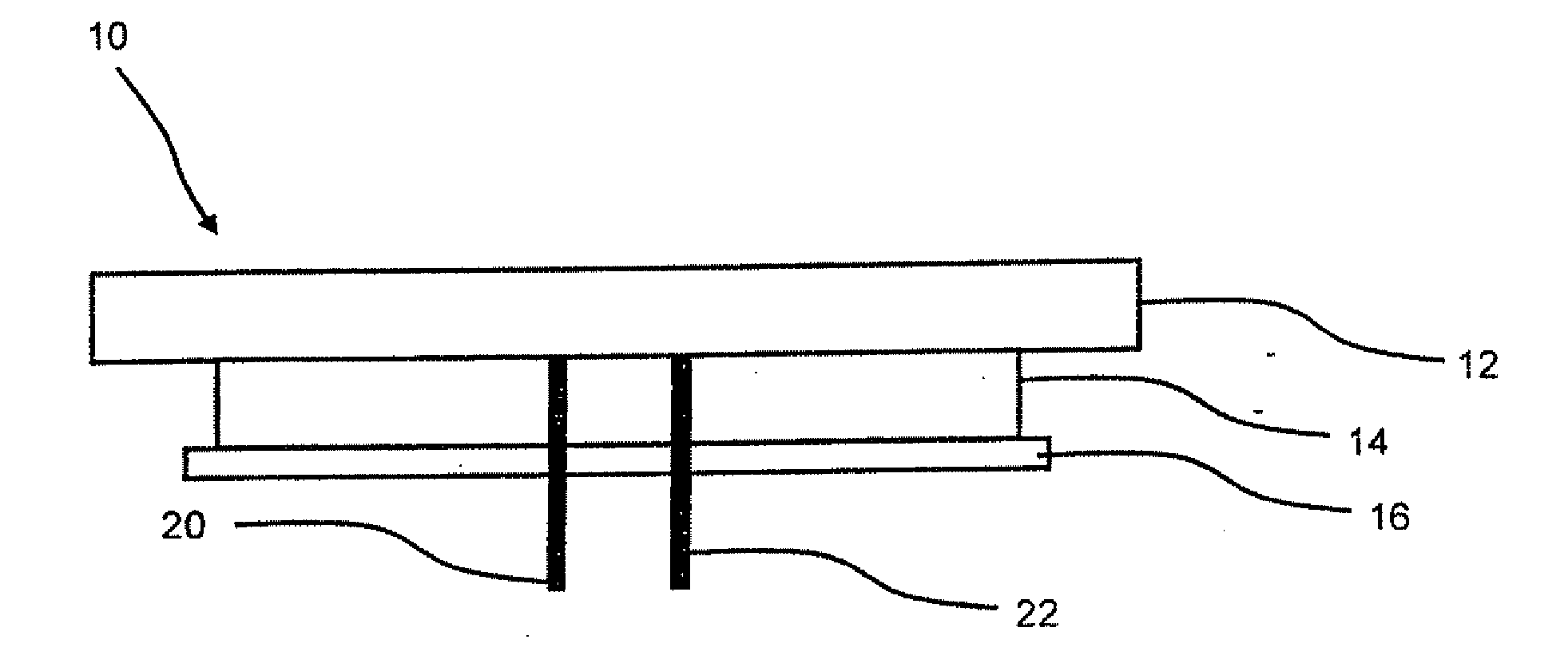
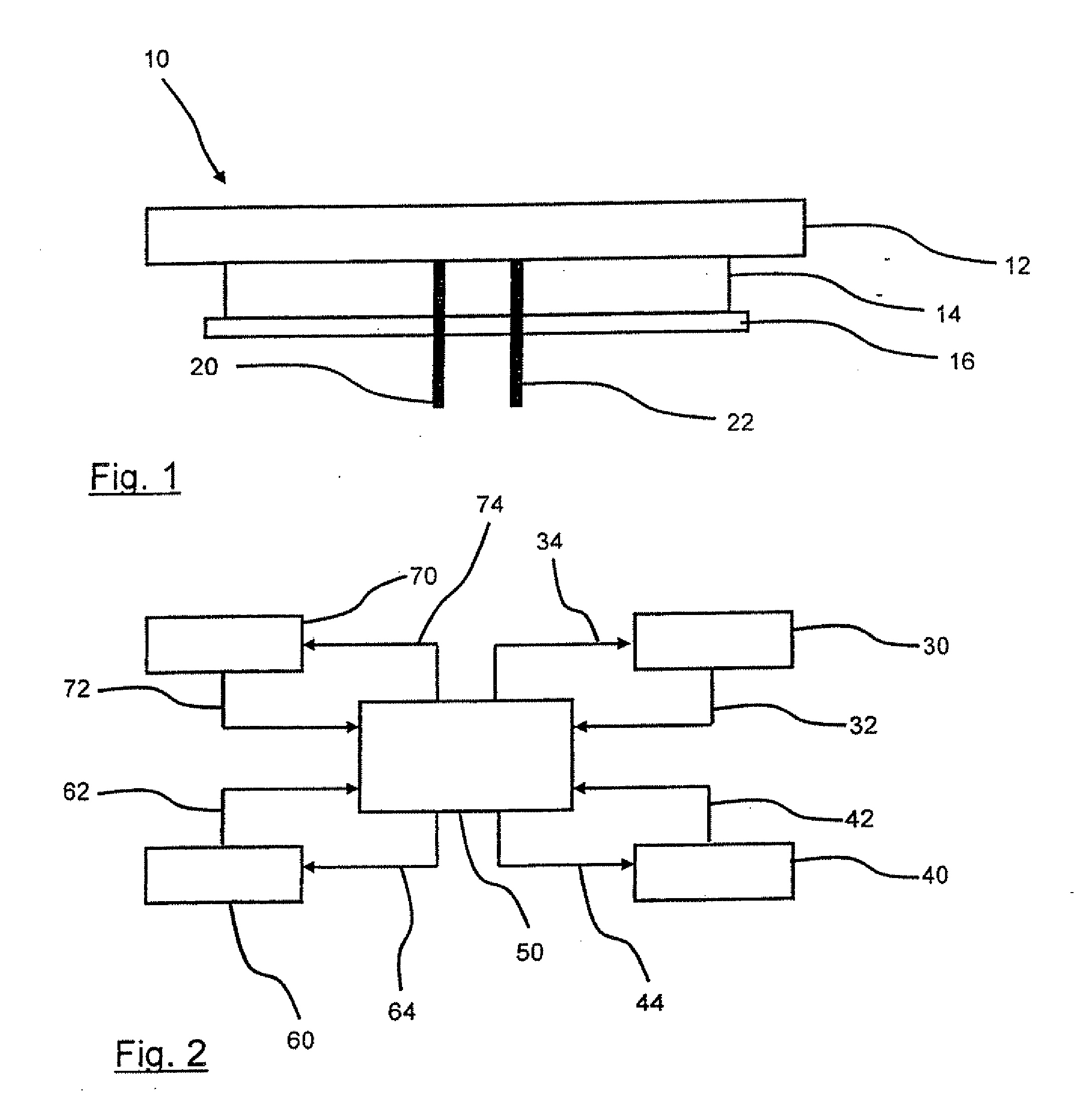
[0055]The brake device 10 according to FIG. 1 has a rotatably mounted brake disc 12 and a friction lining 14 that can be engaged with the brake disc 12, said friction lining 14, in turn, being arranged on a lining carrier plate 16. For purposes of exerting a braking action, the brake lining consisting of the lining carrier plate 16 and the friction lining 14 is pressed from the top against the rotating brake disc 12 so that the flat friction surfaces of the brake disc 12 and the friction lining 14 rub against each other in order to bring about the friction force necessary for the braking.

[0056]Two electric conductors 20, 22 are fed from the rear—in the depiction according to FIG. 1 from below—through the brake lining 14. The faces of these electric conductors 20, 22, which are made of different materials, are flush with the friction surface of the friction lining 14. The two electric conductors 20, 22 form a thermocouple together with the brake disc 12—which is configured to be elec...


PUM


Abstract

A temperature and/or wear sensor for brake or clutch devices is designed as a thermocouple in which the conductors (20, 22) that are electrically insulated from each other are arranged inside a friction lining (14) and can be connected to each other so as to be electrically conductive by means of a rotatably mounted brake element (12), clutch element or the like, with which the friction lining can be engaged in order to brake or to depress the clutch (FIG. 1). The conductors can be coupled to an electric oscillating circuit.

Description

CROSS-REFERENCE TO RELATED APPLICATIONS[0001]This application is a national stage application (under 35 U.S.C. § 371) of PCT / EP2007 / 007314, filed Aug. 18, 2007, which claims benefit of German application 10 2006 039 590.5, filed Aug. 23, 2006.DESCRIPTION[0002]The invention relates to a temperature sensor and a wear sensor for brake or clutch devices, particularly for automotive brakes or clutches. The invention further relates to a brake system equipped with such sensors, and to a method for controlling such a brake or clutch system.STATE OF THE ART[0003]Brakes such as, for instance, automotive brakes configured as disc brakes, sometimes warm up or heat up considerably during the braking operation. In this process, the brake components involved, such as the brake lining and the brake disc, can heat up to more than 100° C. [212° F.]. Especially in the case of several braking operations shortly one after the other, the high temperature that prevails at the brake means that the requisi...

Claims


Application Information

Patent Timeline
IPC IPC(8): G06F19/00F16D66/02F16D66/00
CPCB60T8/268B60T17/22F16D2066/001F16D66/027F16D66/02
Inventor DEGENSTEIN, THOMAS
Owner TMD FRICTION SERVICES
Why Eureka
Try Eureka