Large area solar cell

a solar cell and large-area technology, applied in the field of solar cells, can solve the problem of relative poor conductivity of materials used

Inactive Publication Date: 2010-01-28
SOLARMER ENERGY INC +1
View PDF10 Cites 27 Cited by
  • Summary
  • Abstract
  • Description
  • Claims
  • Application Information

AI Technical Summary

Problems solved by technology

This decrease is due to the relatively poor conductivity of materials used when fabricating

Method used


Image

  • Large area solar cell
  • Large area solar cell
  • Large area solar cell

Examples


Embodiment Construction

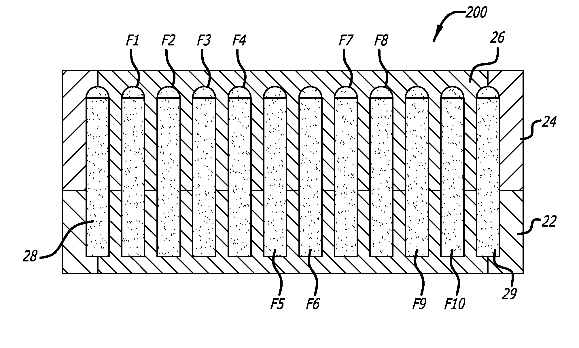
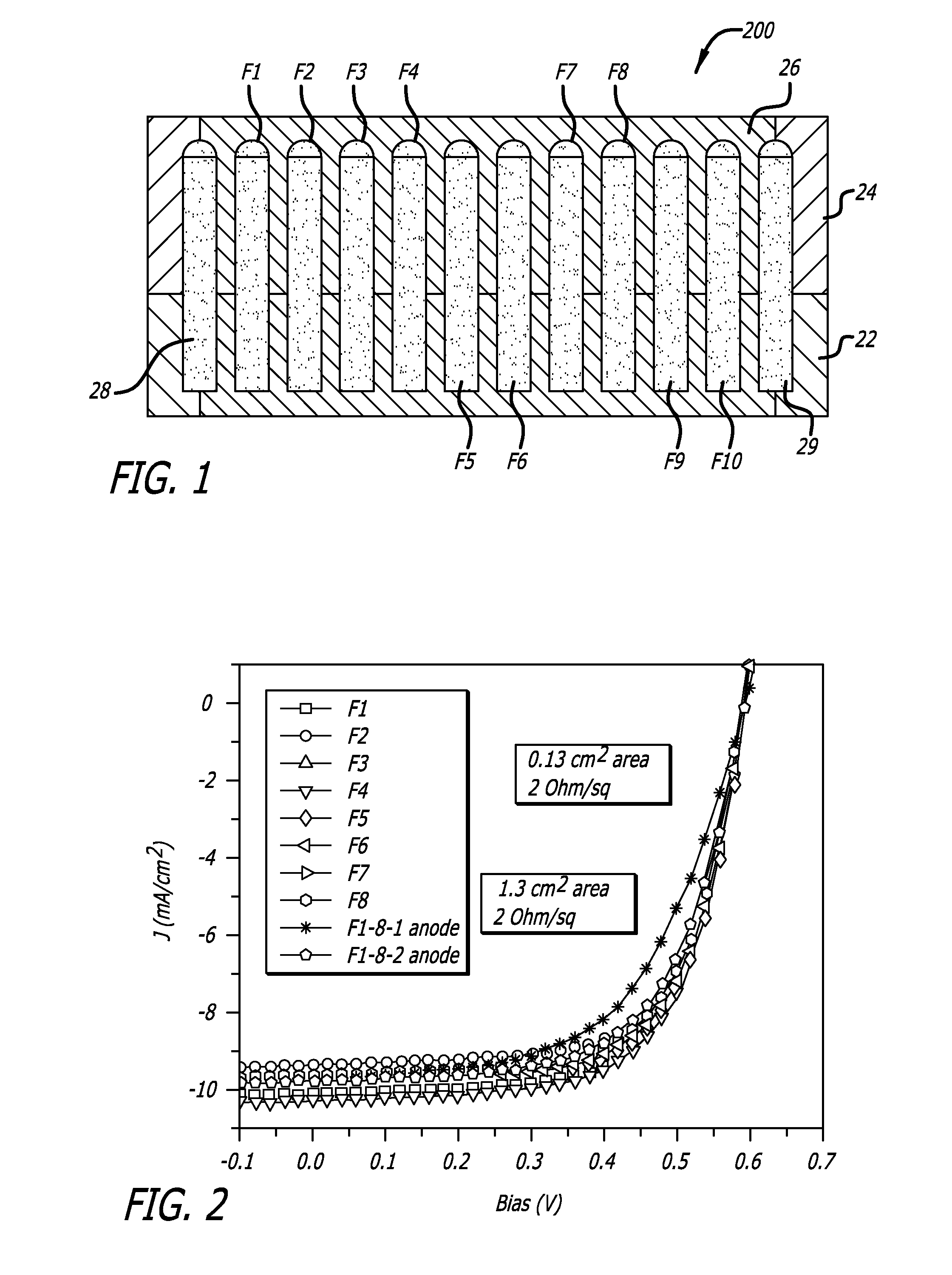
[0018]Referring to FIG. 1, there is a solar cell 200 in accordance with one embodiment of the present disclosure. The solar cell 200 has an active layer 26, which absorbs sunlight and converts it into electricity. The active layer 26 is located between electrodes F1-F10 and 22 that are stacked on a mechanically stable substrate and there are anode fingers 28 and 29 in direct electrical contact with the electrode 22.

[0019]Referring to FIG. 2, there are current-voltage curves for the solar cell 200 shown in FIG. 1. The first eight curves are for isolated electrodes F1 through F8 while only utilizing anode 28 as the positive contact. The photocurrent (9.3±0.3 mA / cm2) and Voc were kept substantially the same. As the distance from the anode 28 increases, the fill-factor of the solar cell 200 reduces from 66.4% in the first electrode F1 to 65.4% in the eighth electrode F8. The J-V curves indicate a varied series resistance between the different electrodes F1 through F8 in the range of 10 ...


PUM

PropertyMeasurementUnit
Electrical conductivityaaaaaaaaaa
Electrical resistanceaaaaaaaaaa
Ratioaaaaaaaaaa

Abstract

A polymer solar cell has an anode, cathode and an active layer. The anode has a surface area larger than the cathode. On the anode, in the area with no cathode, is a conducting element in electrical contact with the anode, having a higher conductivity than the anode and substantially surrounding the cathode in order to minimize the distance between any two points on the cathode and the conducting element. The conducting element allows electrons to travel a shorter distance in the anode and through a higher conducting path to an electrical contact.

Description

BACKGROUND[0001]1. Field[0002]This disclosure relates, in general, to solar cells and more particularly to organic solar cells.[0003]2. General Background[0004]As the area of a polymer solar cell increases, the series resistance to the flow of electrons increases and, subsequently, the cells' performance (PCE %) decreases. This decrease is due to the relatively poor conductivity of materials used when fabricating the anodes of polymer solar cells compared to the anodes of their non-polymer counterparts.[0005]It is, therefore, an object of the present disclosure to provide a conduit for the unobstructed flow of electrons to charge collection contacts.SUMMARY[0006]In one aspect of the present disclosure, there is an anode for a solar cell, provided as a layer, on a substrate. Stacked on top of the anode are an active layer and a cathode.[0007]The anode is larger in surface area than the area of the cathode. A conducting element in electrical contact with the anode is provided on the a...

Claims


Application Information

Patent Timeline
IPC IPC(8): H01L31/0352
CPCH01L27/302Y10T29/49002Y02E10/549H01L51/445H10K30/57H10K30/83
Inventor SHROTRIYA, VISHALIRVIN, CASEYLI, GANGYANG, YANG
Owner SOLARMER ENERGY INC
Why Eureka
Try Eureka