Wvt design for reduced mass and improved sealing reliability

a fuel cell and water vapor transfer technology, applied in the direction of cell components, heating types, separation processes, etc., can solve the problems of increased material and manufacturing costs, increased manufacturing time of membrane humidifiers, and high ohmic voltage loss

Active Publication Date: 2010-01-28
GM GLOBAL TECH OPERATIONS LLC
View PDF44 Cites 27 Cited by
  • Summary
  • Abstract
  • Description
  • Claims
  • Application Information

AI Technical Summary

Benefits of technology

[0018]The above, as well as other advantages of the present invention, will become readily apparent to those skilled in the art fr

Problems solved by technology

For example, lower water content of the membrane leads to a higher proton conduction resistance, thus resulting in a higher ohmic voltage loss.
By utilizing the web for support of the plates and flow channels,

Method used


Image

  • Wvt design for reduced mass and improved sealing reliability
  • Wvt design for reduced mass and improved sealing reliability
  • Wvt design for reduced mass and improved sealing reliability

Examples


Embodiment Construction

[0033]The following detailed description and appended drawings describe and illustrate various exemplary embodiments of the invention. The description and drawings serve to enable one skilled in the art to make and use the invention, and are not intended to limit the scope of the invention in any manner. In respect of the methods disclosed, the steps presented are exemplary in nature, and thus, the order of the steps is not necessary or critical.

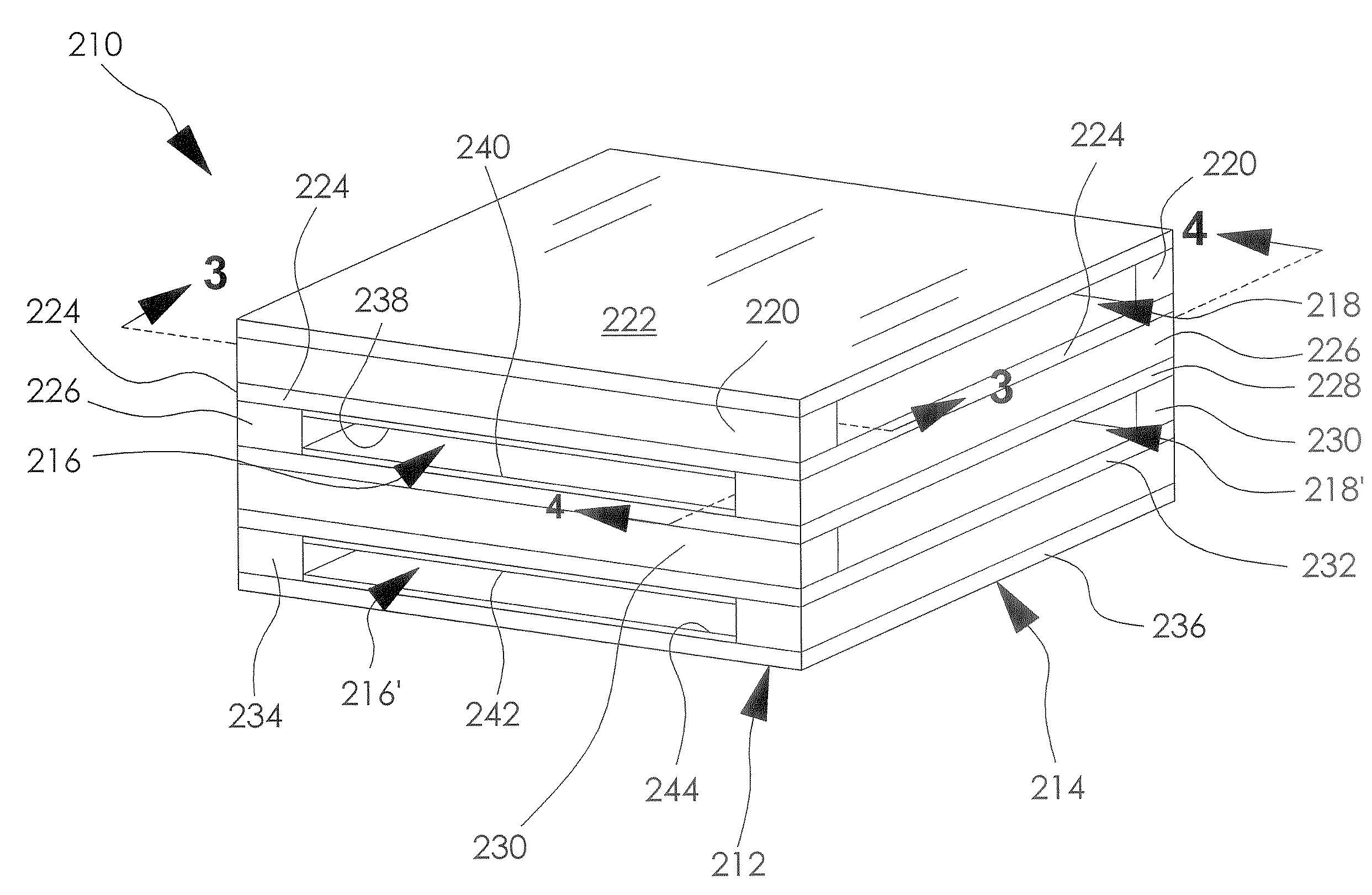
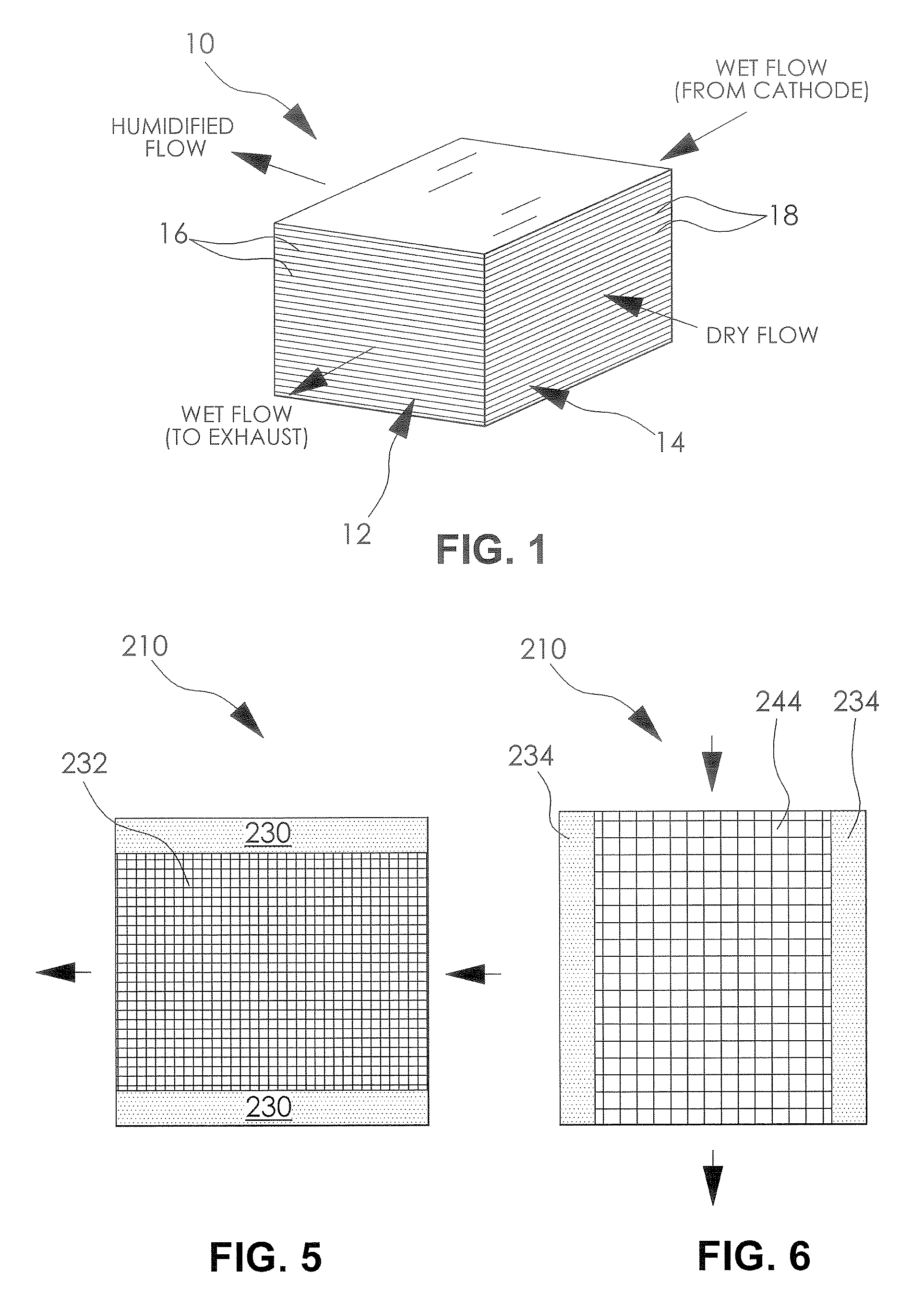
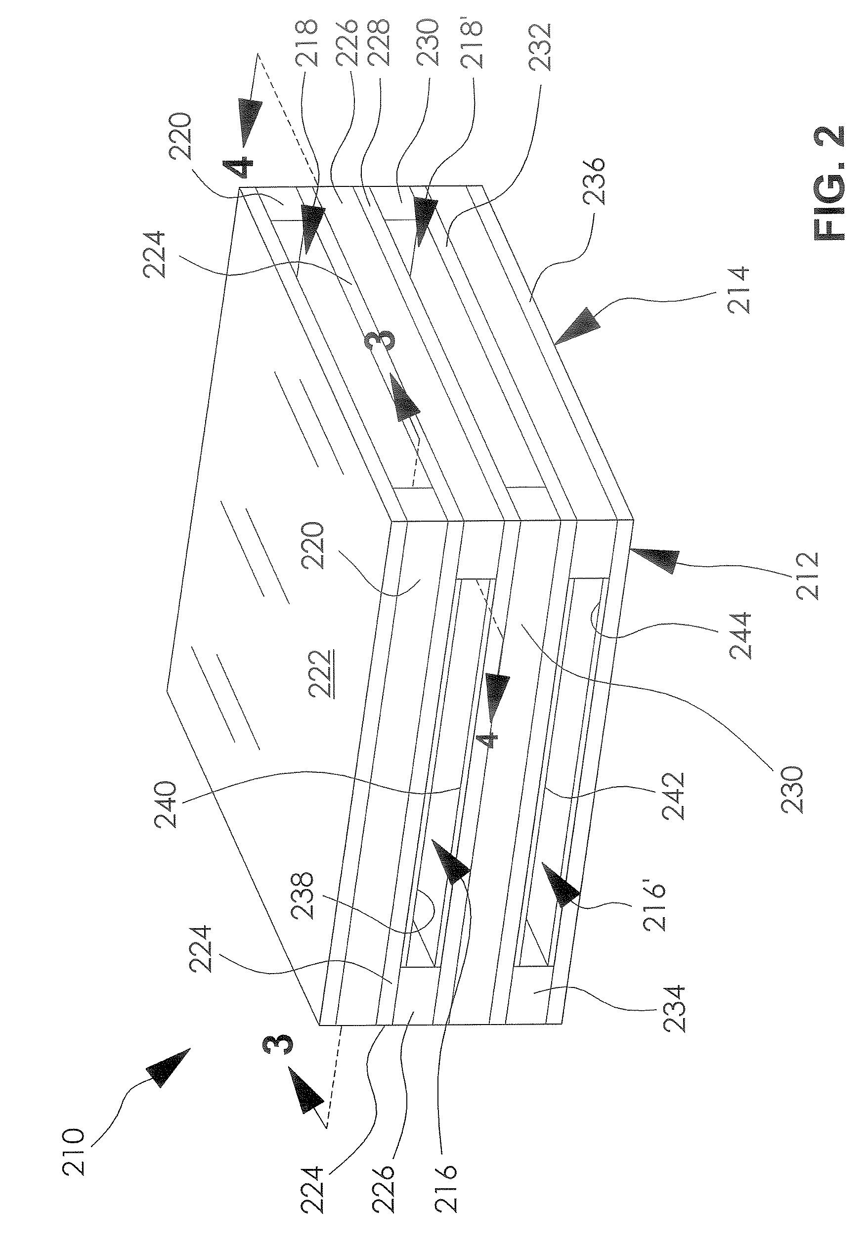
[0034]FIG. 1 schematically illustrates a membrane humidifier 10 for a cathode side of a fuel cell system (not shown). However, it is understood that the membrane humidifier 10 can be used for an anode side of the fuel cell system or otherwise as desired. The membrane humidifier 10 includes a wet side 12 adapted to receive a wet fluid, and a dry side 14 adapted to receive a dry fluid. As used herein, wet fluid means a fluid such as air and gas mixtures of O2, N2, H2O, and H2, for example, including water vapor and / or liquid water therein at a...


PUM

PropertyMeasurementUnit
Pressureaaaaaaaaaa
Massaaaaaaaaaa
Sensitivityaaaaaaaaaa

Abstract

A membrane humidifier for a fuel cell system is disclosed wherein the membrane humidifier includes a plurality of membrane layers, a first pair of spaced apart sealing bars disposed between a first membrane layer and a second membrane layer adjacent to perimeter edges thereof to form a first flow channel, a second pair of spaced apart sealing bars disposed between the second membrane layer and a third membrane layer adjacent to perimeter edges thereof to form a second flow channel, and a plurality of supports, wherein a first support is disposed adjacent the second planar layer and extending between the second pair of spaced apart sealing bars, and a second support is disposed adjacent the third planar layer and extending between the second pair of spaced apart sealing bars.

Description

FIELD OF THE INVENTION[0001]The invention relates to a fuel cell system and more particularly to water vapor transfer unit for a fuel cell system.BACKGROUND OF THE INVENTION[0002]Fuel cell systems are increasingly being used as a power source in a wide variety of applications. Fuel cell systems have been proposed for use in power consumers such as vehicles as a replacement for internal combustion engines, for example. Such a system is disclosed in commonly owned U.S. patent application Ser. No. 10 / 418,536, hereby incorporated herein by reference in its entirety. Fuel cell systems may also be used as stationary electric power plants in buildings and residences, as portable power in video cameras, computers, and the like. Typically, the fuel cell systems generate electricity used to charge batteries or to provide power for an electric motor.[0003]Fuel cells are electrochemical devices which directly combine a fuel such as hydrogen and an oxidant such as oxygen to produce electricity. ...

Claims


Application Information

Patent Timeline
IPC IPC(8): B01F3/04H01M2/00H01M8/04B23P15/00
CPCY10T29/494H01M8/04126Y02E60/50
Inventor ROBB, GARY M.GOEBEL, STEVEN G.
Owner GM GLOBAL TECH OPERATIONS LLC
Why Eureka
Try Eureka