Radar with non-uniformly spaced antenna array

a technology of uniform spacing and antenna array, applied in the field of radars, can solve the problems of increasing the number of antennas, increasing the cost difficulty in narrowing the space between adjacent antennas of uniform spacing antenna array, so as to reduce the effect of undesired peas, reducing the possibility of erroneous estimation, and deteriorating the estimation accuracy of azimuth

Active Publication Date: 2010-01-28
DENSO CORP
View PDF16 Cites 40 Cited by
  • Summary
  • Abstract
  • Description
  • Claims
  • Application Information

AI Technical Summary

Benefits of technology

[0052]In summary, conventional radars equipped with a non-uniformly spaced antenna array in place of a uniformly spaced antenna array may increase the possibility of erroneously estimating azimuths of targets due to undesired peaks, thus deteriorating the estimation accuracy of azimuths of t

Problems solved by technology

However, because the azimuth resolution of the uniformly spaced antenna array is determined by the length of the aperture thereof to maintain high the azimuth resolution of the uniformly spaced antenna array with the FOV being wide contributes to an increase in the number of antennas; this results in an increase in the cost of the uniformly spaced antenna array.
In addition, it may be difficult to narrow the spaces between adjacent antennas of the uniformly spaced antenna array because the narrowing causes the number of antennas and mutual coupling between the antennas to increase.
More specifically, in radars equipped with such a non-uniformly spaced antenna array, not only appear desired peaks, but also appear peaks due to noise and undesired peaks.
Thus, in these radars equipped with a non-uniformly spaced antenna array, when azimuths of power estimation targets corresponding to the number

Method used


Image

  • Radar with non-uniformly spaced antenna array
  • Radar with non-uniformly spaced antenna array
  • Radar with non-uniformly spaced antenna array

Examples


first embodiment

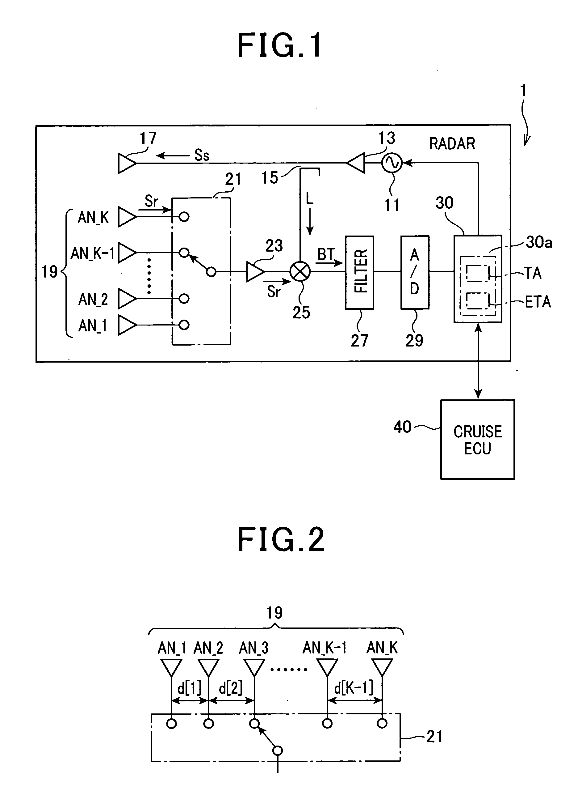
[0084]Referring to FIG. 1, there is illustrated a radar 1 according to the first embodiment of the present invention. In the first embodiment, the radar 1 is installed in a motor vehicle and mounted on, for example, the front end of the motor vehicle.

[0085]The radar 1 is designed as an FMCW (Frequency-Modulated Continuous-Wave) radar. Specifically, the radar 1 is provided with an oscillator 11, an amplifier 13, a distributor 15, a transmitting antenna 17, and a receiving antenna array 19.

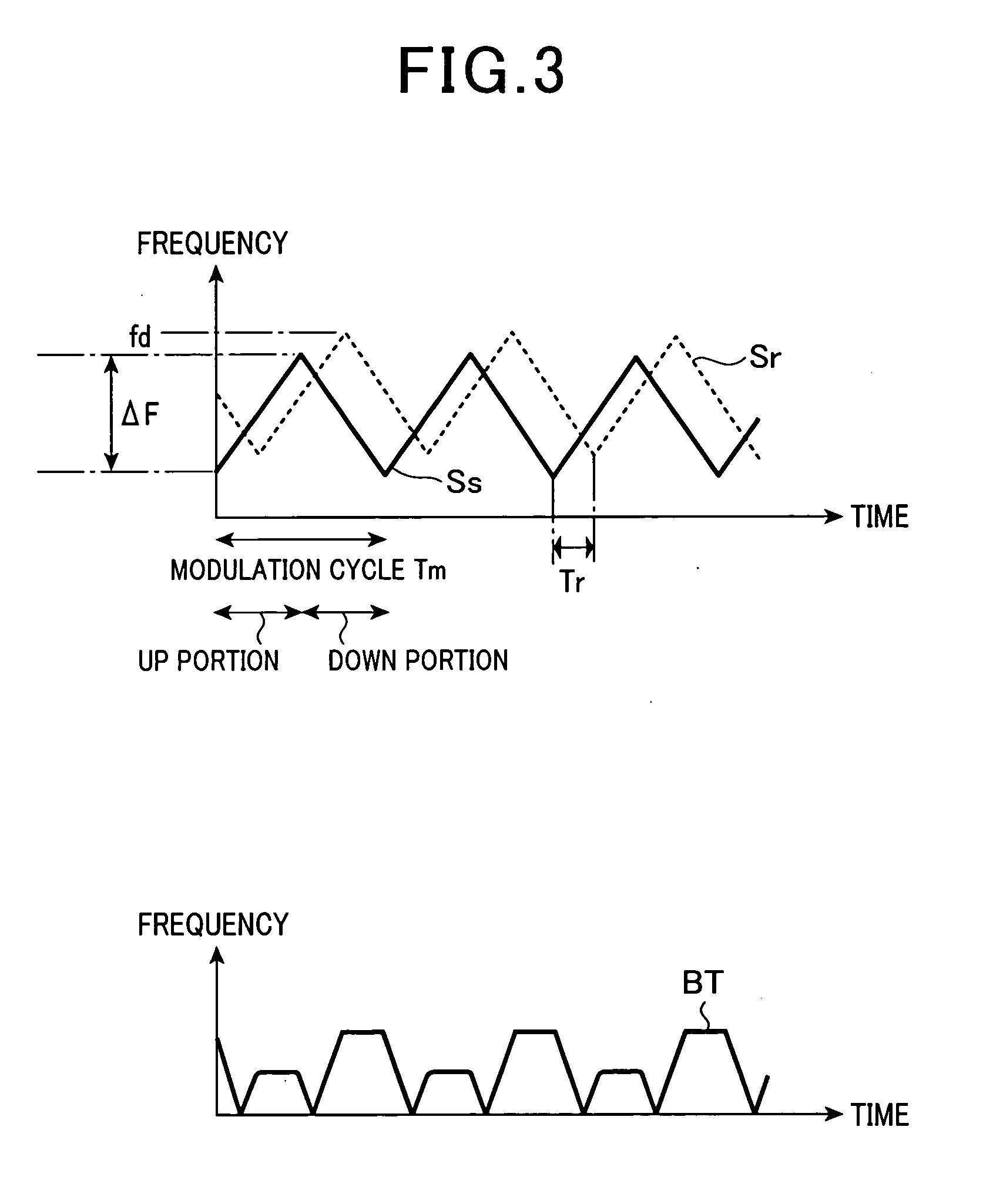
[0086]The oscillator 11 works to generate, based on a triangular modulation voltage signal, a millimeter high-frequency signal; the frequency of the millimeter high-frequency signal is linearly changed, within a preset frequency range ΔF, in a positive sense (up chirp) and a negative sense (down chirp) over time with a preset modulation cycle Cm.

[0087]The amplifier 13 works to amplify the millimeter high-frequency signal generated by the oscillator 11.

[0088]The distributor 15 works to distribute the...

second embodiment

[0210]A radar according to the second embodiment of the present invention will be described hereinafter with reference to FIGS. 10A, 10B, and 11.

[0211]The structure of the radar according to the second embodiment is substantially identical to that of the radar 1 according to the first embodiment except for the following different points. So, like parts between the radars according to the first and second embodiments, to which like reference characters are assigned, are omitted or simplified in description.

[0212]The radar 1 according to the first embodiment is designed to eliminate azimuths corresponding to undesired peaks that appear in the MUSIC spectrum based on the threshold correction table TA in which the appropriate values TD[1], . . . , TD[Q] of the threshold power level Pth corresponding to the evaluation levels RM+i are stored.

[0213]Note that there are constant patterns in principle between azimuths in which undesired peaks appear and azimuths in which peaks except for the ...

third embodiment

[0243]A radar according to the third embodiment of the present invention will be described hereinafter with reference to FIGS. 12A, 12B, and 13.

[0244]The structure of the radar according to the third embodiment is substantially identical to that of the radar according to the first or second embodiment except for the following different points. So, like parts between the radars according to the first or second embodiment and the third embodiment, to which like reference characters are assigned, are omitted or simplified in description.

[0245]The radar according to the third embodiment includes an evaluation-level table ETA stored in the memory unit 30a of the signal processor 30. The evaluation-level table ETA is illustrated in FIG. 1 by phantom line (chain double dashed line) so that the evaluation-level table ETA can be omitted in the radar 1 according to the first embodiment.

[0246]The signal processor 30 according to the third embodiment is programmed to carry out a correlation det...


PUM


Abstract

In a radar with a non-uniformly spaced antenna array, an extractor estimates a number of arrivals of echoes to the antenna array. A setter sets a number of azimuths corresponding to a number of extracted peaks as a number of tested azimuths greater than the number of arrivals of echoes by a preset number. A determiner determines a level of correlations among steering vectors respectively corresponding to the tested azimuths. A selector selects, from the tested azimuths, azimuths as power-estimation targets based on the determined level of the correlations among the steering vectors. A first estimator estimates a received power level from each power-estimation target. A second estimator estimates, from the power-estimation targets, an azimuth of the target based on the estimated received power level from each power-estimation target. The estimated received power level from the azimuth is equal to or greater than a preset threshold level.

Description

CROSS REFERENCE TO RELATED APPLICATIONS[0001]This application is based on Japanese Patent Application 2008-193764 filed on Jul. 28, 2008. This application claims the benefit of priority from the Japanese Patent Application, so that the descriptions of which are all incorporated herein by reference.FIELD OF THE INVENTION[0002]The present invention relates to radars for transmitting radio waves, receiving echoes reflected from targets, and estimating, based on the received echoes, the directions of the targets in azimuth.BACKGROUND OF THE INVENTION[0003]Radars are widely used for motor vehicles. Specifically, such a radar installed in a motor vehicle works to emit radio waves from a transmitting antenna, receive, by a receiving antenna array, echoes reflected from targets. The receiving antenna array consists of a plurality of antennas in array.[0004]The radar works to analyze the received echoes to thereby estimate the range to each target, the azimuth direction of each target with r...

Claims


Application Information

Patent Timeline
IPC IPC(8): G01S13/00G01S13/931
CPCG01S3/74G01S13/345G01S2013/9375H01Q3/24H01Q21/22G01S13/931G01S2013/93271
Inventor MIZUTANI, AKIYOSHISUZUKI, KOICHIRO
Owner DENSO CORP
Why Eureka
Try Eureka