Self calibrating cable for high definition digital video interface

a digital video interface and self-calibration technology, applied in the field of high-speed cables, can solve the problems of increased risk of misinterpreting received data at the receiver end of the cable, adverse effect of high-speed signals carried by the cable,

Active Publication Date: 2010-01-28
REDMERE TECH
View PDF19 Cites 36 Cited by
  • Summary
  • Abstract
  • Description
  • Claims
  • Application Information

AI Technical Summary

Benefits of technology

[0007]Therefore there is an object of the present invention to provide a system for calibrating a high speed cable carrying...

Problems solved by technology

The inherent characteristics and manufacturing imperfections of high-speed differential signaling cables such as may be used to carry HDMI signals have an adverse effect on the hig...

Method used


Image

  • Self calibrating cable for high definition digital video interface
  • Self calibrating cable for high definition digital video interface
  • Self calibrating cable for high definition digital video interface

Examples


Embodiment Construction

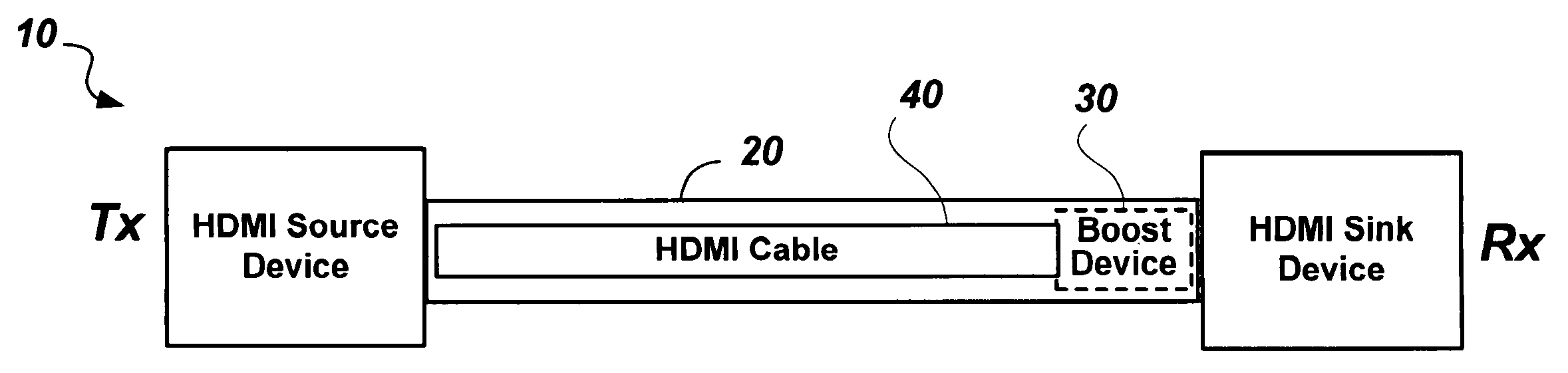
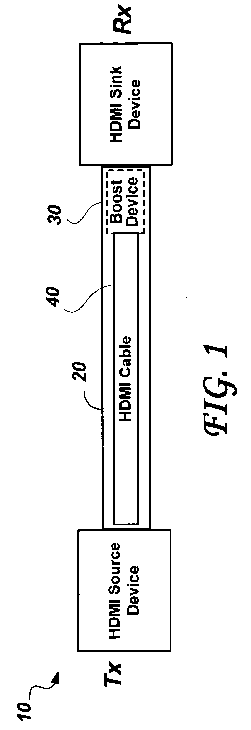
[0092]FIG. 1 shows an HDMI system 10 including an improved HDMI cable 20. The HDMI system 10 includes an HDMI transmitter Tx (HDMI Source Device), an HDMI receiver Rx (HDMI Sink Device), and the improved HDMI cable 20 connecting the Tx to the Rx.

[0093]The improved HDMI cable 20 comprises an embedded boost device 30 and a basic (passive) HDMI cable 40. The boost device 30 is located near the end of the improved HDMI cable 20 closest to the HDMI receiver Rx. The improved HDMI cable 20 may be used to connect a DVD player to a Television Screen for example, or in general connect any HDMI Source Device to an HDMI Sink Device.

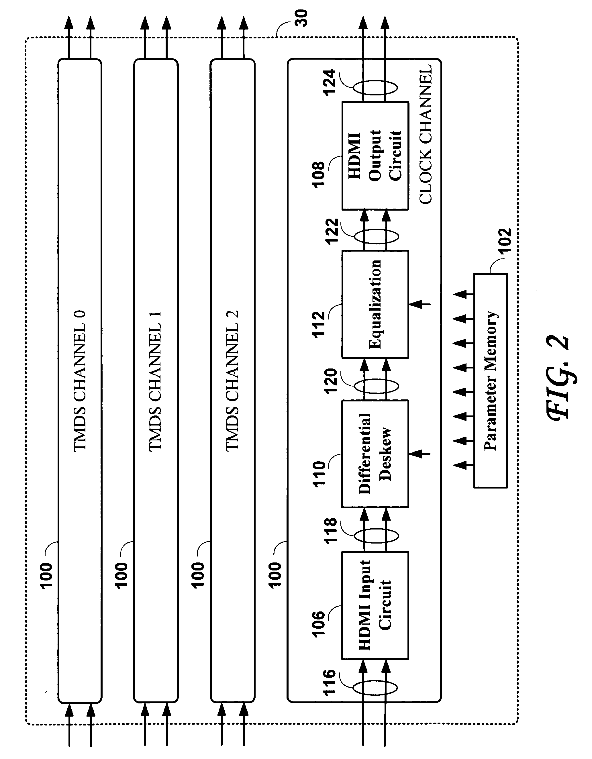
[0094]FIG. 2 shows a block diagram of circuits that are included in the boost device 30 of the HDMI system 10 of FIG. 1. The boost device 30 includes a number of channel boost circuits 100, and a parameter memory 102. Typically, the boost device 30 includes four (4) channel boost circuits 100, each to boost the signal of one of the TMDS Channel 0, the TMDS Channel 1,...


PUM


Abstract

A High Definition Multi-Media Interface (HDMI) cable may exhibit frequency dependent signal attenuation, inter symbol interference, and inter-pair skew. A boost device integrated with the cable can compensate for such impairments of the cable. A self calibrating cable with a boost device of the embodiment of the invention is described, in which parameters that control the response of the boost device are set optimally in a self-calibrating process comprising looping the boosted cable on itself through a calibration fixture that contains a calibration control device. The boost device includes pattern generators and a sampling circuit. Each high speed channel of the cable is separately tested and calibrated with the help of one of the other channels serving as a sampling channel. Additional embodiments provide for a selected replica boost device and a distinct pattern generator device in the calibration fixture.

Description

RELATED APPLICATIONS[0001]The present application is a Continuation-in-Part (CIP) of the U.S. application Ser. No. 12 / 219,642 filed on Jul. 25, 2008 entitled “Self Calibrating Cable For A High Definition Digital Video Interface”. The present application claims benefit from the U.S. provisional application Ser. No. 60 / 935,080 to Horan, John et al. filed on Jul. 25, 2007 entitled “Circuits and Methods for Gigabit Data Recovery and Digital Repeater Implementation”, and U.S. application Ser. No. 12 / 219,642 filed on Jul. 25, 2008 entitled “Self Calibrating Cable For A High Definition Digital Video Interface”, both applications being incorporated herein by reference.FIELD OF THE INVENTION[0002]The present invention relates to high speed cables that carry serially encoded differential signals between electronic equipments, and in particular, multi-conductor cables with embedded boost devices for interconnecting audio-visual equipment.BACKGROUND OF THE INVENTION[0003]The distribution of tel...

Claims


Application Information

Patent Timeline
IPC IPC(8): H04N17/00
CPCG09G5/006G09G2300/0426G09G2320/0693G09G2370/12H04L25/242H04L1/243H04L25/0272H04L25/03885H04L1/205
Inventor HORAN, JOHN MARTINKEANE, JOHN ANTHONYGUTHRIE, GERARD DAVID
Owner REDMERE TECH
Why Eureka
Try Eureka