Monopole acoustic transmitter ring comprising piezoelectric material

a technology of piezoelectric material and acoustic transmitter, which is applied in the direction of instruments, measurement devices, seismology, etc., can solve the problems of further limiting space, restricting the measurement range, and the relationship between the ring diameter and the frequency so as to improve the tool mode signal and reduce the effect of the effect of the output acoustic pressure puls

Inactive Publication Date: 2010-01-28
PRECISION ENERGY SERVICES
View PDF13 Cites 14 Cited by
  • Summary
  • Abstract
  • Description
  • Claims
  • Application Information

AI Technical Summary

Benefits of technology

[0013]One or more openings in the wall of the collar provide a path of pressure pulses from the transmitter to pass into the borehole environs. A tradeoff between the number, dimensions, and location of the openings is made to obtain the best measurement and the highest output possible while still maintaining mechanical integrity of the collar structure. For example, having four large openings spaced azimuthally at 90 degrees from each other maximizes the pressure signal amplitude but can result in signal distortion at a receiver array due to the different paths acoustic pressure waves take to arrive at a receiver array aligned azimuthally and disposed on the side of the receiver section of the collar. This effect can be minimized by matching the number and azimuthal location of the receiver elements to the number and azimuthal location of the openings.
[0016]One of the major advantages of using a piezoelectric ring transmitter oriented as previously defined is the optimization of acoustic pressure pulse output. Even with some of the ring output blocked by the tool wall or deactivated in a segmented ring comprising non piezoelectric material, the formation signal from a ring transmitter is still higher than other types of transmitters that can be mounted in the wall of a drill collar.
[0018]The fact that a ring is mounted inside the drill collar and the sound waves are emitted only through openings in the collar causes part of the signal to transmit directly into the collar body. This can cause an increase in tool mode signal, which is undesirable. Several methods can be used to reduce this effect.
[0019]One of the major advantages of using a ring transmitter is its optimization of signal output. Even with some of the ring signal blocked by the tool body or deactivated in a segmented ring, the pressure signal reaching the borehole environs is still typically greater than other types of transmitters that are be mounted within or in the wall of a drill collar.

Problems solved by technology

There are several restrictive challenges in disposing a piezoelectric ring transmitter in a LWD tool.
This conduit further limits the space needed to mount a ring transmitter element in a plane perpendicular to the major axis of the tool.
Another limitation is the relationship between the ring diameter and frequency of the output acoustic pressure pulse.

Method used


Image

  • Monopole acoustic transmitter ring comprising piezoelectric material
  • Monopole acoustic transmitter ring comprising piezoelectric material
  • Monopole acoustic transmitter ring comprising piezoelectric material

Examples


first embodiment

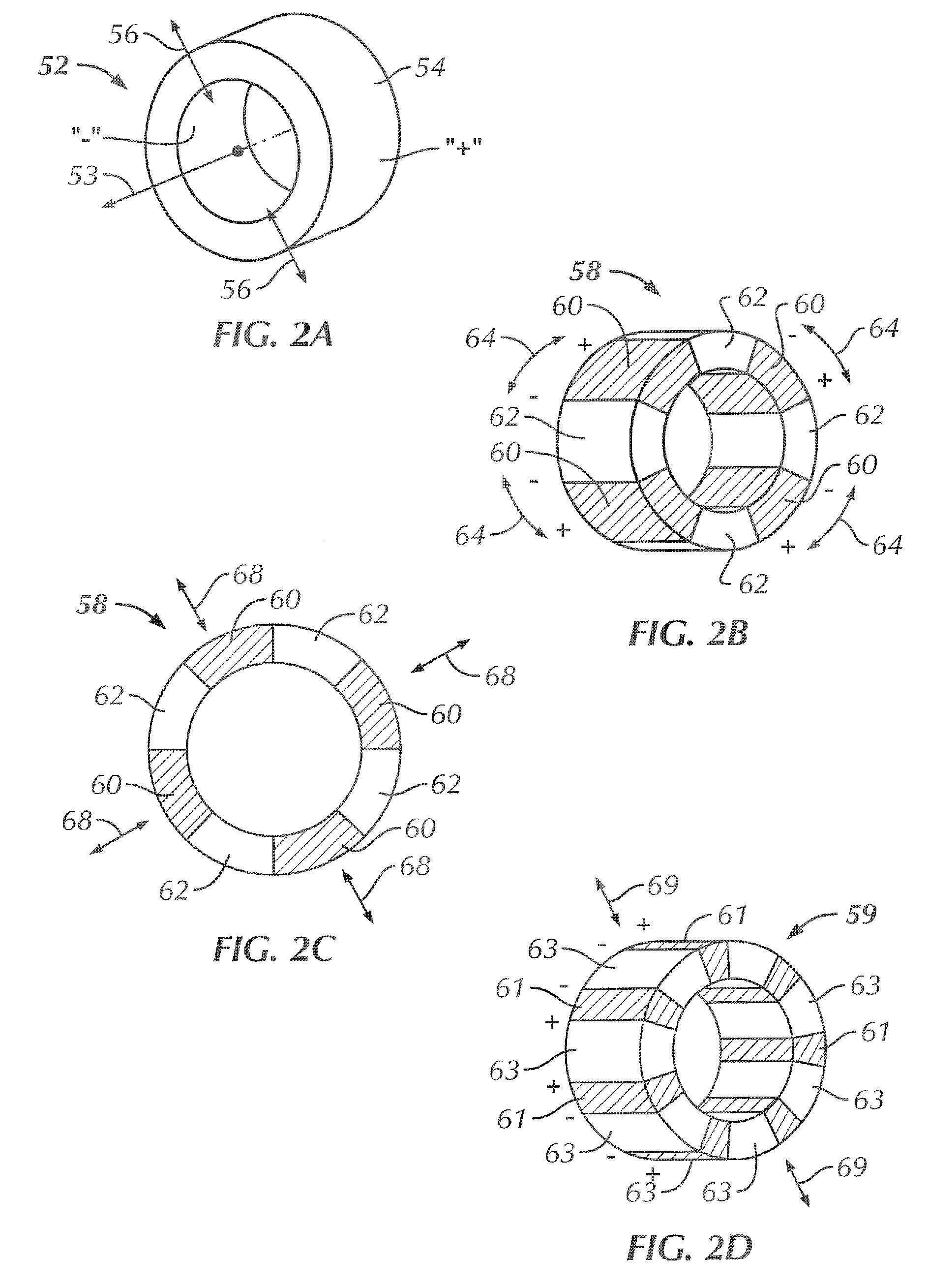
[0039]the transmitter ring 52 is illustrated in perspective in FIG. 2a and comprises a single loop of piezoelectric material 54. This embodiment of the transmitter ring will be referred to as a “continuous” ring embodiment. The polarization of the ring is indicated by “+” and “−”. Electrical connections to the piezoelectric material 54 (see FIG. 3) are such that the ring 52 expands or contracts upon application of a voltage. As an example, a positive voltage applied the outer and inner surfaces of the ring 52 expands the ring outward in the radial direction, while a negative voltage contracts the ring in the axial direction. This expansion and contraction is illustrated conceptually by the arrows 56. The normal of the transmitter ring, in this and other disclosed embodiments, is illustrated by the arrow 53.

second embodiment

[0040]the transmitter ring 58 is illustrated in perspective in FIG. 2b, and comprises a plurality of arc segments 60 of piezoelectric material with intervening arc segments 62 of material. This embodiment will be referred to as a “segmented” ring. For a given ring dimension, intervening arc segments 62 of relatively light material, such as alumina, increase output frequency. Conversely, intervening arc segments of relatively heavy materials, such as tungsten, decrease output frequency. The polarization of each segment 60 of each piezoelectric segment is again indicated by “+” and “−”. Electrical connections are such that the same voltage is applied simultaneously to each piezoelectric segment 60. Each segment 60 expands and contracts simultaneously in an azimuthal direction illustrated conceptually by the arrows 64.

embodiment 58

[0041]FIG. 2c is a cross sectional view of the segmented ring embodiment 58. Since all segments are rigidly bound to one another, the azimuthal expansions and contractions (see arrows 64) of the piezoelectric segments 60 result in a radial expansion and contraction of the segmented ring 58. The ring expansion and contraction is illustrated conceptually by the arrows 68.

[0042]FIG. 2d illustrates the “striped” ring embodiment 59. The embodiment comprises continuous ring piezoelectric ring 63 on which active arc segments are polarized or polled. This is accomplished by applying, to the surfaces of the ring 63, bands 61 or “stripes” of electrode material 61 thereby defining active arc segments. The active arc segments of piezoelectric material are polarized by the bands of electrode material 61 as indicated by “+” and “−” annotations. The entire striped ring 59 is activated simultaneously, as opposed to the segmented ring embodiment 58 in which certain segments of piezoelectric material...


PUM


Abstract

A monopole acoustic transmitter for logging-while-drilling comprising as a ring that comprises one or more piezoelectric arc segments. The ring is oriented in a plane whose normal is essentially coincident with the major axis of a logging tool in which it is disposed. The ring disposed within a recess on the outer surface of a short, cylindrical insert. The insert is inserted into a drill collar, rather than into the wall of the collar. The ring can comprise a continuous ring of piezoelectric material, or alternately arc segments or active ring segments of piezoelectric ceramic bonded to segments of other materials such as alumina to increase the frequency or heavy metals such as tungsten to reduce the frequency. The material and dimensions of the material used in-between the piezoelectric segments is chosen to alter the frequency of the ring.

Description

FIELD OF THE INVENTION[0001]This invention is related to systems for measuring an acoustic property of material penetrated by a well borehole. More particularly, the invention is related to improved acoustic transmitters for use with acoustic logging-while-drilling (LWD) or measurement-while-drilling (MWD) borehole assemblies.BACKGROUND[0002]Acoustic logging systems are routinely used in the oil and gas industry to measure formation acoustic properties of earth formation penetrated by a well borehole. These properties include the compressional and shear velocities of the formation, which are subsequently used to determine a variety of formation parameters of interest such as porosity and pore pressure. Additionally, acoustic logging systems are used to produce acoustic images of the borehole from which well conditions and other geological features can be investigated. Other applications of acoustic logging measurements include seismic correlation and rock mechanic determination.[000...

Claims


Application Information

Patent Timeline
Patent Type & Authority Applications(United States)
IPC IPC(8): G01V1/40
CPCG01V1/44
Inventor MICKAEL, MEDHAT W.JONES, DALE A.
Owner PRECISION ENERGY SERVICES
Why Eureka
Try Eureka