Method and system for polarization supported optical transmission

a technology of optical transmission and polarization support, applied in the field of optical communication, can solve the problems of high-speed transmission system drastic pmd degradation, qpsk and similar formats, and cannot be used in much beyond 100 gbit/s, and achieve the effect of effective compensation of polarisation effects and double capacity

Inactive Publication Date: 2010-01-28
OFIDIUM PTY LTD
View PDF16 Cites 112 Cited by
  • Summary
  • Abstract
  • Description
  • Claims
  • Application Information

AI Technical Summary

Benefits of technology

[0010]Advantageously, in one embodiment the method comprises compensating for polarisation effects, for example PMD and PDL, without dynamic physical compensation. In this embodiment, processing of the electrical signals comprises processing of the electrical signals to achieve at least partial compensation of a polarisation effect that has degraded the optical signal before it was received. Processing the electrical signals may comprise constructing a Jones vector of a received OFDM

Problems solved by technology

All of these are barriers to high-speed optical transmission.
For conventional direct-detection single-carrier systems, the impairment induced by a constant differential-group-delay (DGD), a type of PMD, scales with the square of the bit rate, resulting in drastic PMD degradation for high speed t

Method used


Image

  • Method and system for polarization supported optical transmission
  • Method and system for polarization supported optical transmission
  • Method and system for polarization supported optical transmission

Examples


Embodiment Construction

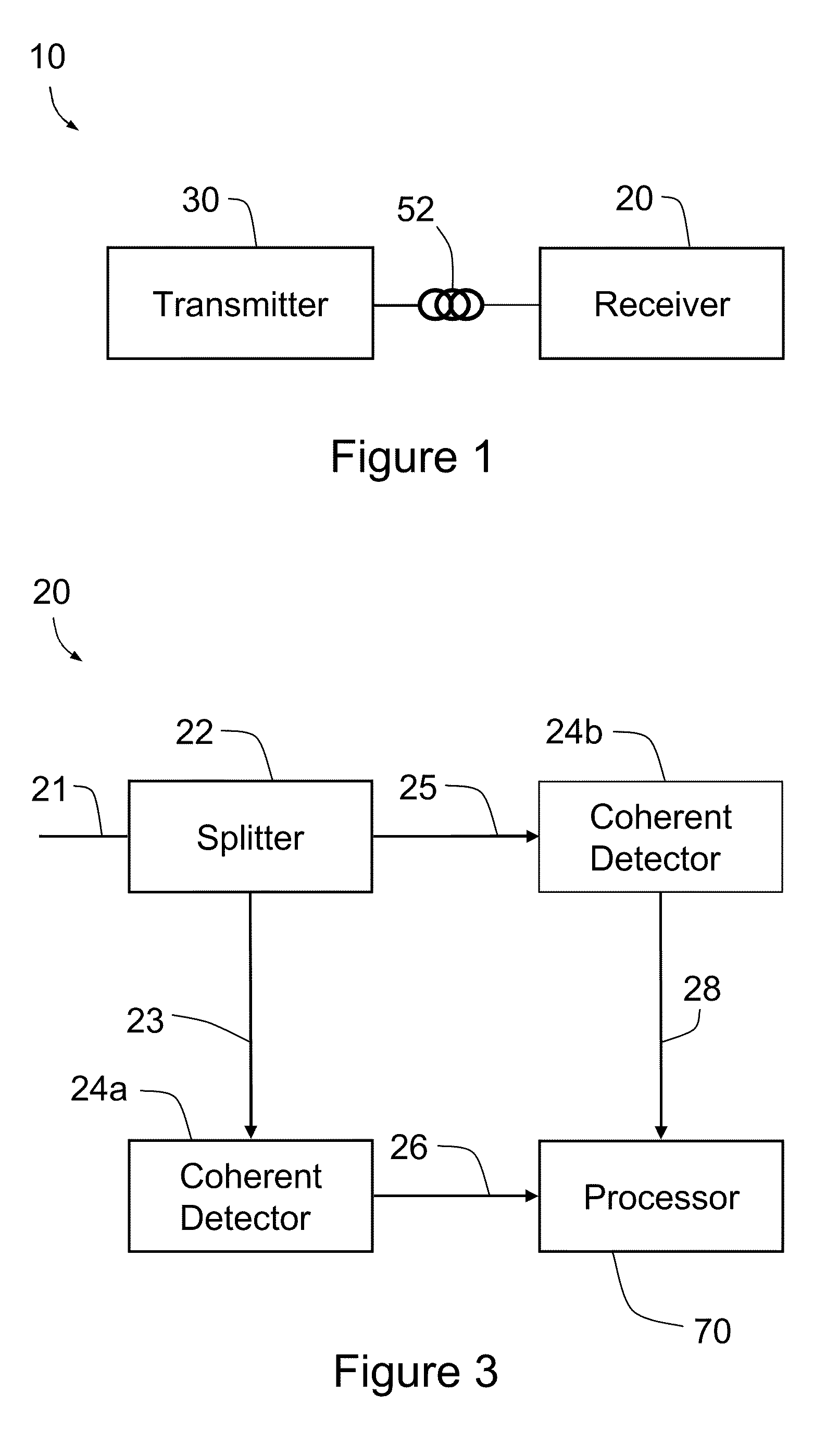
[0071]FIG. 1 is a schematic view of an optical transmission system generally indicated by the numeral 10. System 10 has an optical transmitter 30 and an optical receiver 20. Transmitter 30 and receiver 20 are connected by a waveguide such as an optical fiber 52. In some alternative embodiments some or all of optical fiber 52 may be replaced by free space propagation. Transmitter 30 generates optical signals having Orthogonal Frequency Division Multiplexing (OFDM) modulation. Typically each of the optical signals does not have an optical carrier tone. The signals travel along fiber 52 and are subsequently received by receiver 20. System 10 uses coherent detection, so the transmission scheme used is referred to herein as coherent OFDM (CO-OFDM).

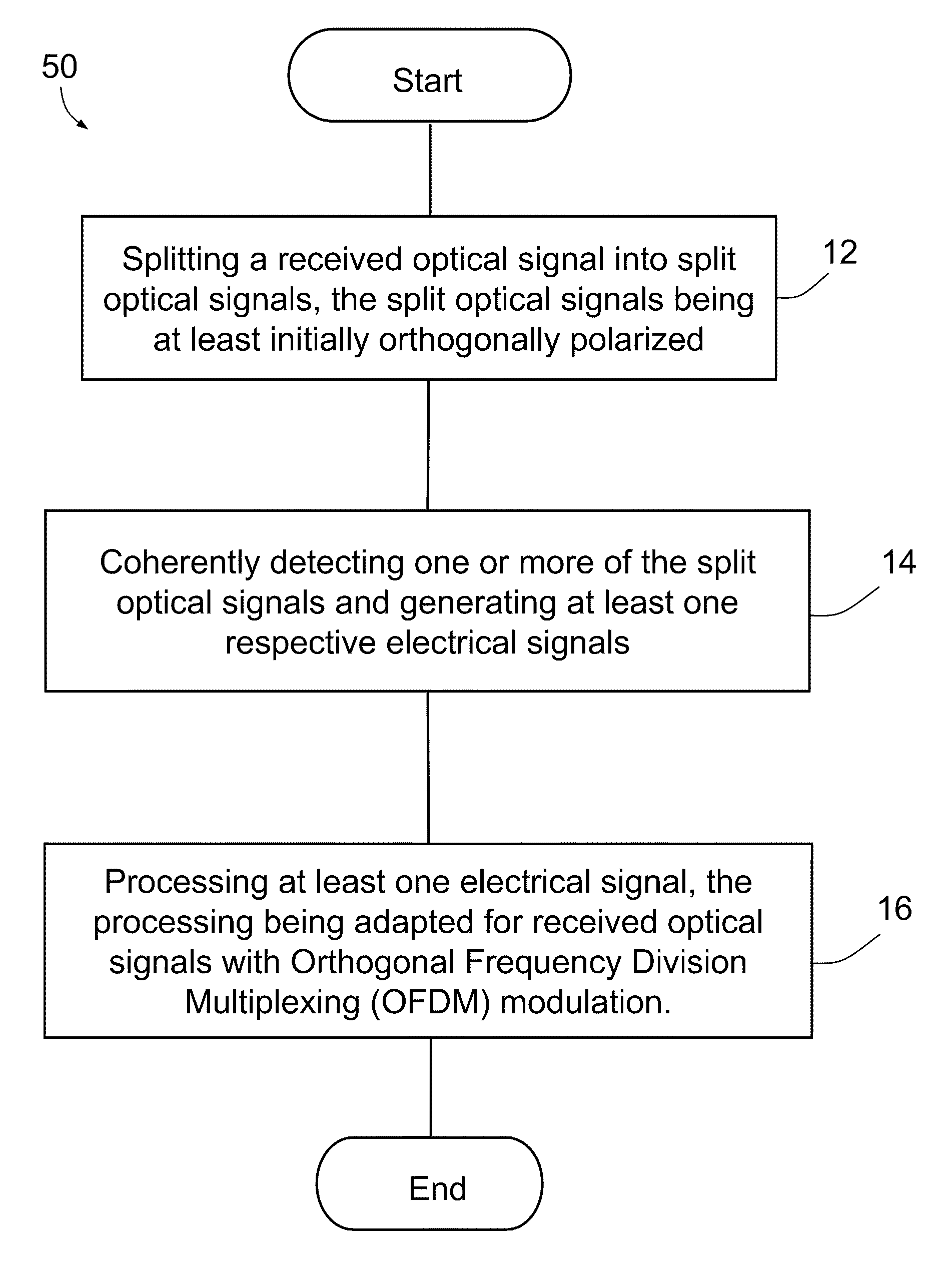
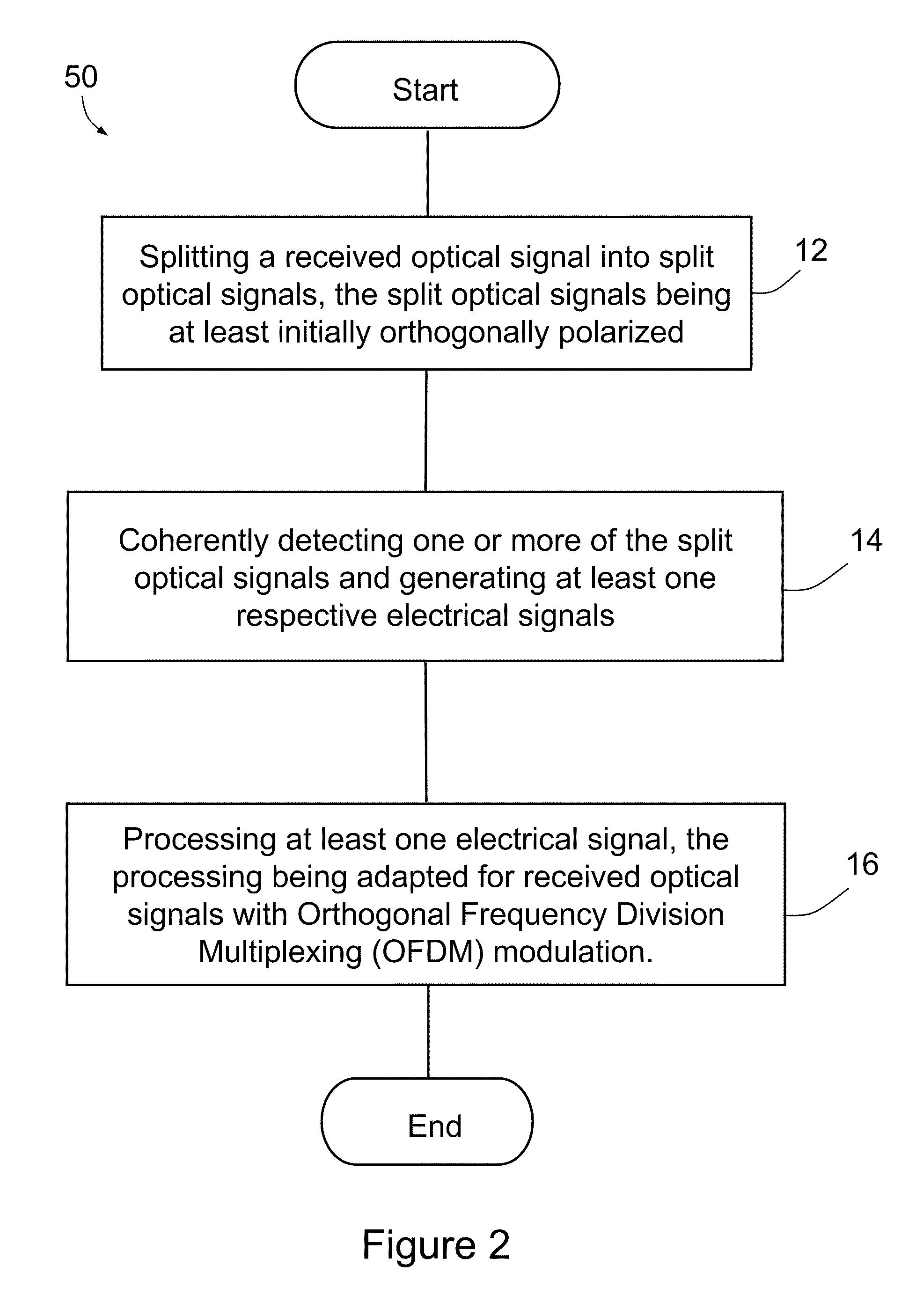
[0072]FIG. 2 is a flow diagram of a method 50 implemented by receiver 20. Method 50 provides detection of the optical signal having OFDM modulation. In this embodiment, method 50 provides resilience against polarization, chromatic and nonlinear...


PUM


Abstract

A method comprising splitting a received optical signal into split optical signals, the split optical signals being at least initially orthogonally polarized, coherently detecting at least one of the split optical signals and generating an electrical signal indicative thereof, and processing said electrical signal, the processing being adapted for received optical signals with orthogonal frequency division multiplexing (OFDM) modulation. A transmission system, a transmitter and a receiver are also provided.

Description

FIELD OF THE INVENTION [0001]The present invention generally relates to optical communications, and particularly but not exclusively to optical signal generation and detection.BACKGROUND OF THE INVENTION [0002]Optical fibers (and other optical waveguides) typically support two polarization modes. The propagation of an optical signal along an optical fiber is influenced by polarization effects including polarization mode dispersion (PMD), coupling (PMC) and loss (PDL), as well as chromatic dispersion (CD). All of these are barriers to high-speed optical transmission. For conventional direct-detection single-carrier systems, the impairment induced by a constant differential-group-delay (DGD), a type of PMD, scales with the square of the bit rate, resulting in drastic PMD degradation for high speed transmission systems.[0003]While progress has been made in realising 100 Gbit / s optical transmission using modulation formats and associated technologies such as Quadrature Phase Shift Keyin...

Claims


Application Information

Patent Timeline
IPC IPC(8): H04J14/06
CPCH04B10/60H04B10/61H04J14/06H04B10/6162H04B10/614
Inventor SHIEH, WILLIAM
Owner OFIDIUM PTY LTD
Why Eureka
Try Eureka