Baffle member for scroll compressors

a scroll compressor and scroll technology, applied in the direction of machines/engines, rotary/oscillating piston pump components, liquid fuel engines, etc., can solve the problems of high wear and substantial amount of lubrication of the surfa

Inactive Publication Date: 2010-01-28
TECUMSEH PROD CO
View PDF34 Cites 27 Cited by
  • Summary
  • Abstract
  • Description
  • Claims
  • Application Information

AI Technical Summary

Benefits of technology

[0006]The present invention provides a baffle member for use in scroll compressors. In one exemplary embodiment, the baffle member is attached to a portion of the crankcase and, in use, deflects lubricant that may be thrown from the thrust surfac

Problems solved by technology

These surfaces tend to experience high wear and us

Method used


Image

  • Baffle member for scroll compressors
  • Baffle member for scroll compressors
  • Baffle member for scroll compressors

Examples


Embodiment Construction

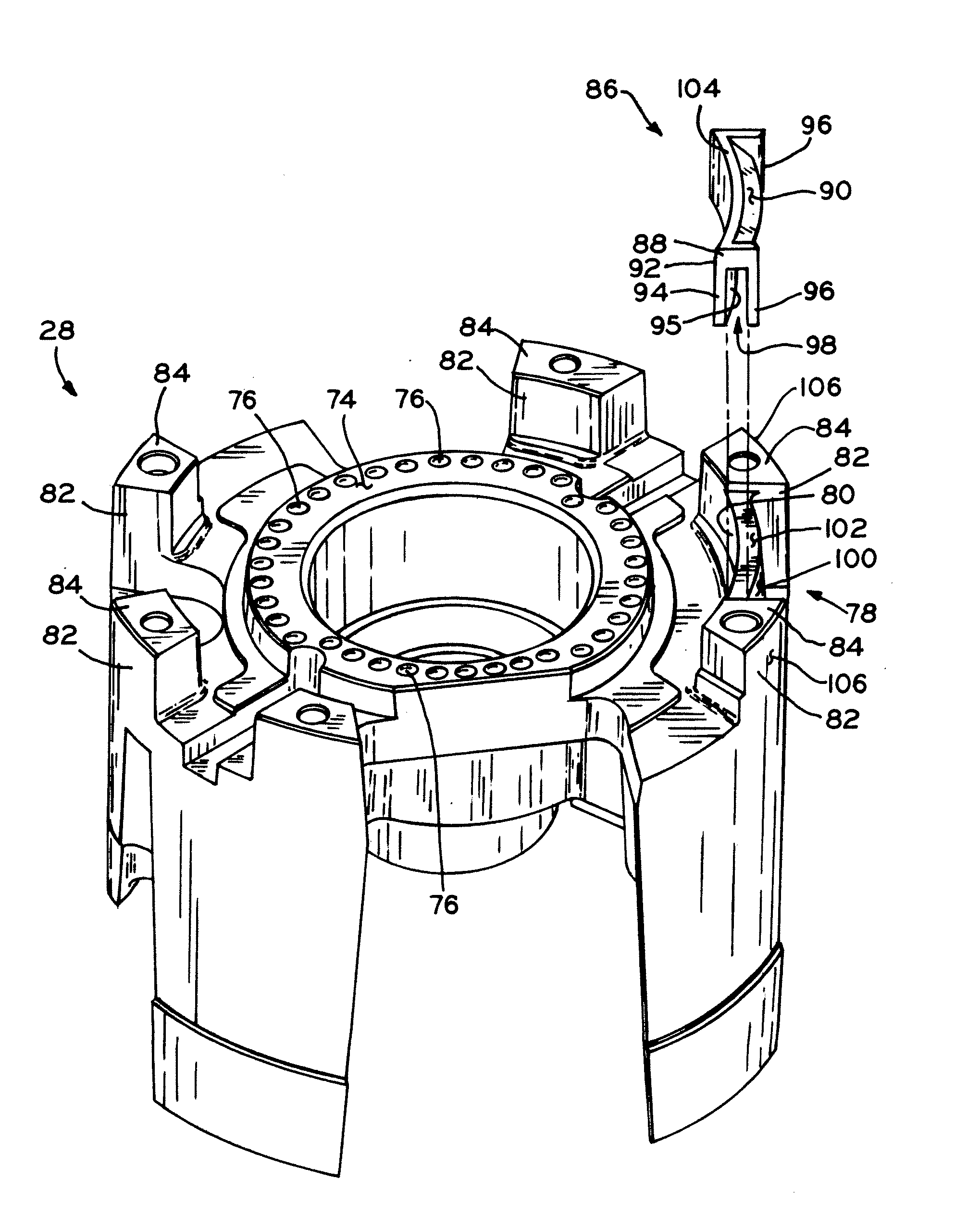
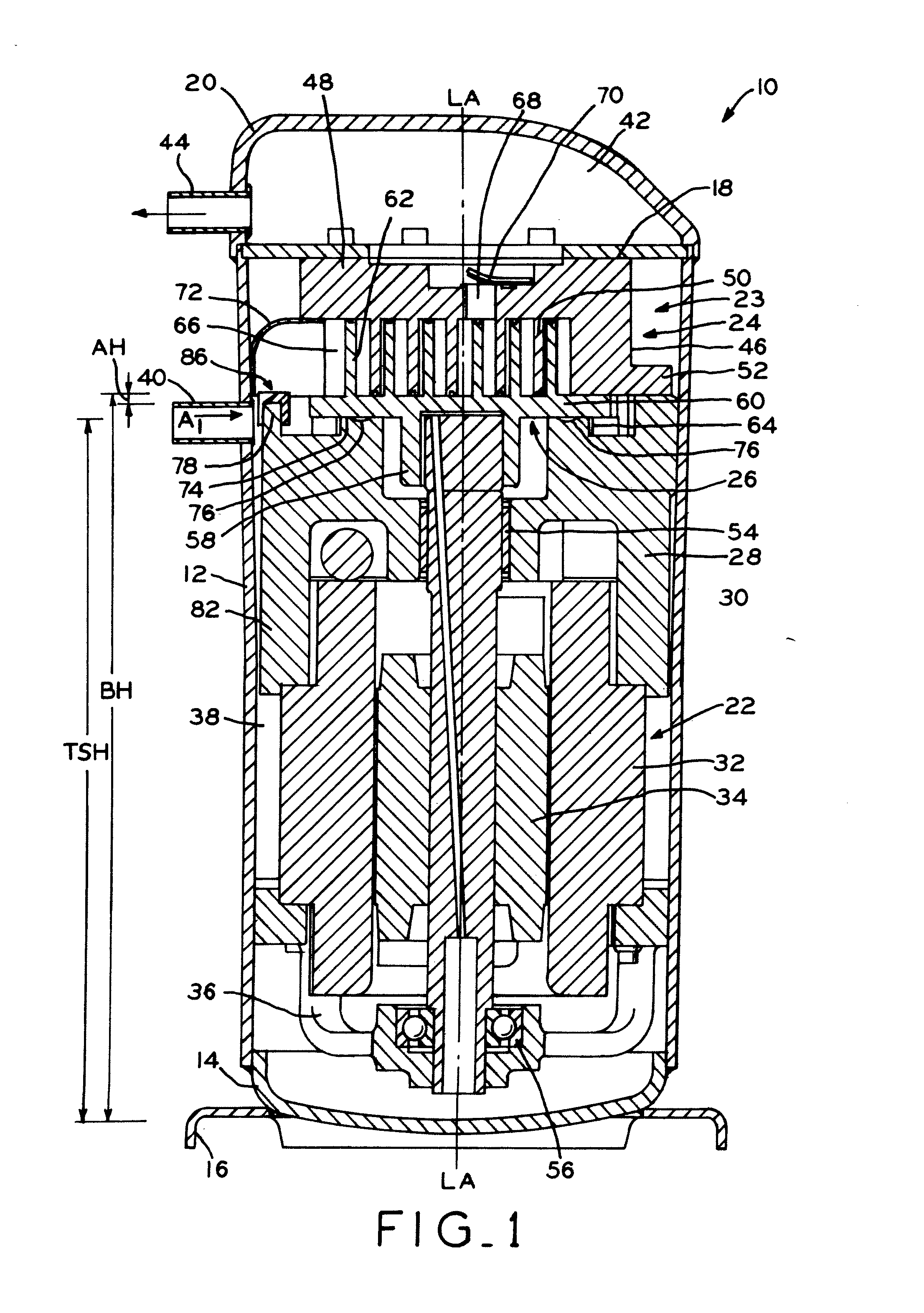
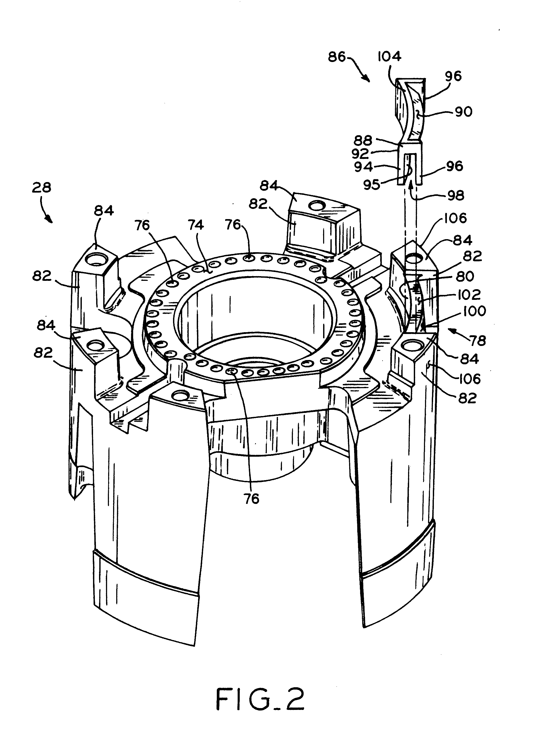
[0022]Referring to FIG. 1, scroll compressor 10 is shown, which includes hermetic main housing 12, bottom cap 14 with base 16 secured to the lower end of housing 12, and a separator plate 18 and top cap 20 each secured to the upper end of housing 12 by a welding, brazing, or other suitable operation to define an enclosed hermetic housing in which motor 22 and compression mechanism 23 of compressor 10 are disposed. Compressor 10 is a vertical compressor generally having an axial direction along the longitudinal axis LA of crankshaft 30, and a radial direction that is perpendicular to the axial direction.

[0023]Motor 22 and compression mechanism 23 generally include first, non-orbiting scroll 24, second, orbiting scroll 26, crankcase 28, crankshaft 30, stator 32, rotor 34, and outboard bearing assembly 36. Separator plate 18 is secured around its perimeter to the interior of housing 12, such as by welding, and divides the interior of the housing 12 into a relatively low pressure suctio...


PUM


Abstract

A baffle member for use in scroll compressors. In one exemplary embodiment, the baffle member is attached to a portion of the crankcase and, in use, deflects lubricant that may be thrown from the thrust surface of the crankcase during operation of the compressor away from the flow of working fluid, and also aids in directing the flow of working fluid away from the thrust surface of the crankcase and toward a suction inlet in the compression mechanism.

Description

CROSS-REFERENCE TO RELATED APPLICATIONS[0001]This application claims the benefit under Title 35 U.S.C. § 119(e) of U.S. Provisional Patent Application Ser. No. 61 / 061,899, entitled LUBRICANT BAFFLE FOR SCROLL COMPRESSORS, filed on Jun. 16, 2008, the entire disclosure of which is expressly incorporated by reference herein.BACKGROUND[0002]1. Field of the Invention[0003]The present invention relates to scroll compressors and, particularly, to a baffle member for a scroll compressor.[0004]2. Description of the Related Art[0005]Compressors generally have mating axially or radially loaded surfaces, such as the interfacing surfaces of thrust bearings and radial bearings. For example, in a scroll compressor, the orbiting scroll member orbits upon a thrust surface that is formed as a portion of the crankcase of the compressor. These surfaces tend to experience high wear and usually require a substantial amount of lubrication. The retention of lubricant on the interfacing bearing surface is o...

Claims


Application Information

Patent Timeline
IPC IPC(8): F04C18/02F04C29/02
CPCF04C18/0215F04C23/008F04C2240/809F04C29/028F04C29/12F04C29/026
Inventor HALLER, DAVID K.
Owner TECUMSEH PROD CO
Why Eureka
Try Eureka