
Lighting device using light-emitting diode and gaming machine including the lighting device

Inactive Publication Date: 2010-01-28
UNIVERSAL ENTERTAINMENT CORP
View PDF16 Cites 32 Cited by
  • Summary
  • Abstract
  • Description
  • Claims
  • Application Information

AI Technical Summary

Benefits of technology

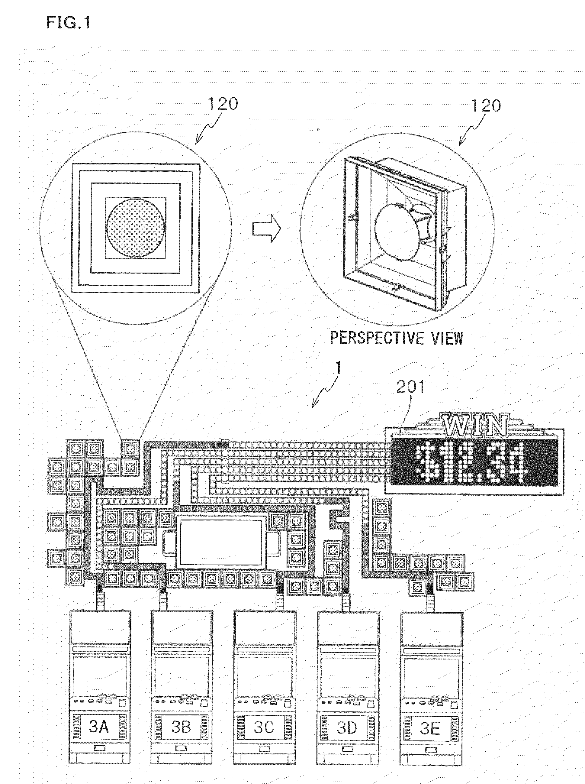
[0017]In this structure, when the light emitted from the light-emitting diode passes through the cover having the metal layer vapor-deposited thereonto, the amount of light is decreased to a predetermined amount. Thus, the amount of light emitted from the light-emitting diode is decreased, so that there can be provided light whose amount is similar to that of a light bulb. Also, it is possible to set the translucency percentage freely by varying the thickness of the metal layer vapor-deposited onto the cover. This allows the amount of light from the light-emitting diode to be adjusted, so that there can be provided light whose amount is similar to that of a light bulb.
[0090]By the housing, the light emitted by the light emitting portion does not emerge outside except through the aperture. In this way, the light emitted by the light emitting portion emerges only through the aperture, making it possible for the players to recognize the luminescent display device emitting light. The players are therefore able to easily grasp the progress of a game, represented by the state of the light emitting portions of the luminescent display devices.

Problems solved by technology

However, using a light bulb for a decorative illumination device may cause high operational cost because the life of a light bulb is relatively short and large power consumption is needed for lighting a bulb.
Although the high directivity of an LED lamp is preferable for the purpose of providing light whose lighting area is limited, the light from an LED produces excessively sharp boundaries between the lighted area and its surroundings (not-lighted area).
Often, the players feel the glare when the light emitted by the luminescent display device is too bright.
However, adjusting the brightness of the luminescent display device can be tedious because the suitable brightness of the emitted light from the luminescent display device varies depending upon lighting conditions such as the room illumination of the place where the gaming machine is installed, or the position of the luminescent display device relative to the players, among other factors.
However, when light from one luminescent display device merges into light from other luminescent display devices, there are cases where the players cannot recognize the luminescent display device emitting light, failing to grasp the game situation.
Since this requires adjustment of illumination area for each luminescent display device, it complicates the whole procedure of adjusting the illumination area of the luminescent display devices.

Method used


Image

  • Lighting device using light-emitting diode and gaming machine including the lighting device
  • Lighting device using light-emitting diode and gaming machine including the lighting device
  • Lighting device using light-emitting diode and gaming machine including the lighting device

Examples


first embodiment

[0141]The following describes a first embodiment of a gaming machine and a playing method thereof according to the present invention. Note that reference numbers and symbols given to members and steps of flowcharts are only applicable to those described within the present embodiment, and do not represent the members or the steps of the other embodiments.

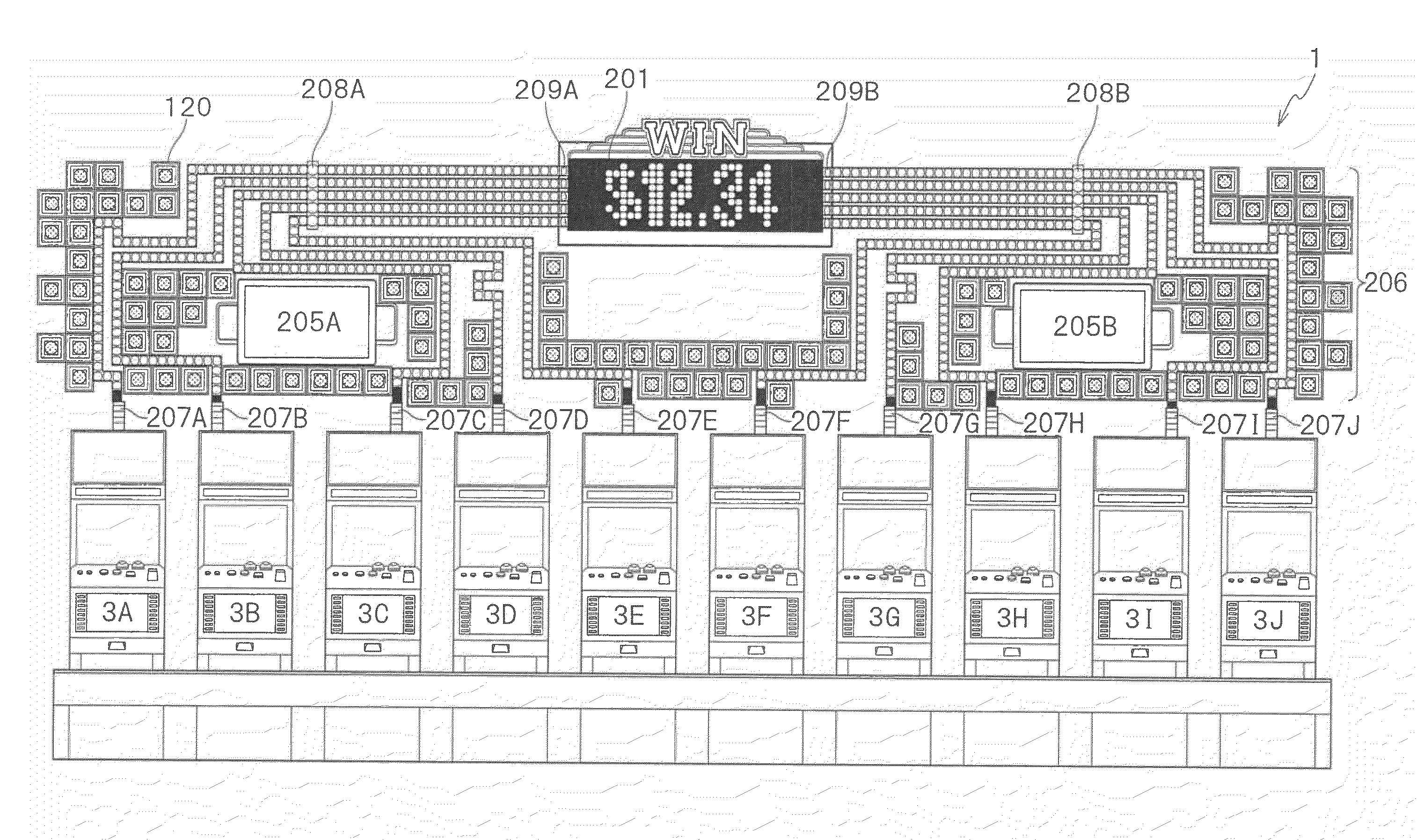
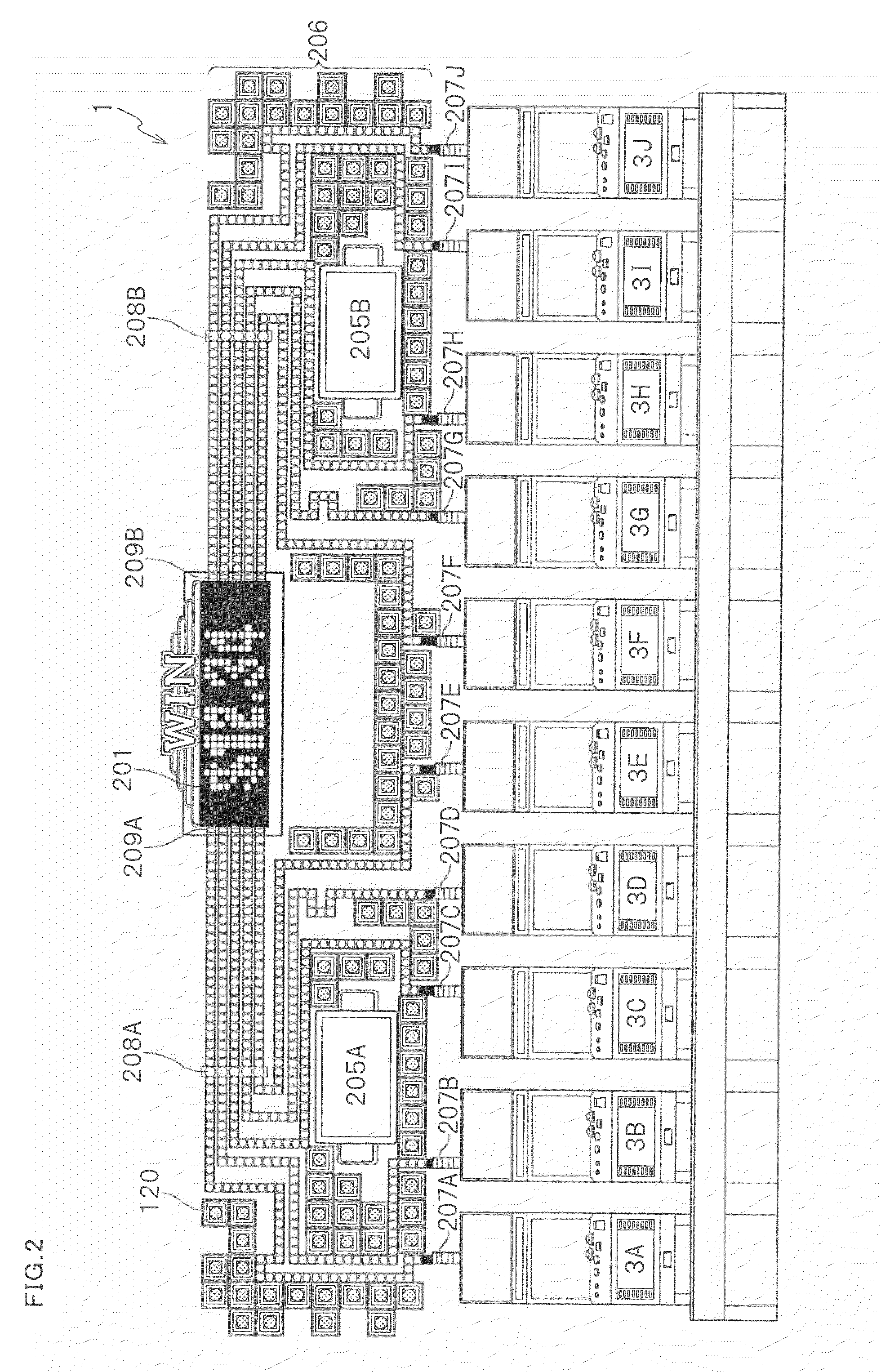
[0142]The followings describe an embodiment of a lighting device and a gaming machine including the lighting device according to the present invention. The below-described first embodiment deals with a case where the lighting device and the gaming machine including the lighting device according to the present invention are applied to a game system 1, by specifically implementing them from mechanical, electrical, and operational aspects.

[0143][Mechanical Structure of Game System 1]

[0144]The game system 1 is installed in a gaming facility or the like. The game system 1 performs a unit game by use of a game value. The game value is a co...

second embodiment

[0315]The following describes another embodiment of a gaming machine and a playing method thereof according to the present invention. Note that reference numbers and symbols given to members and steps of flowcharts in the present embodiment as well as the subsequent embodiments (i.e., third and fourth embodiments) are only applicable to those described within these embodiments, and do not represent the members or the steps of the above mentioned first embodiment.

[0316]As shown in FIG. 22, a luminescent display device 310 is provided in a gaming machine 1. The luminescent display device 310 includes a light emitting portion 311 for emitting light, a housing 314, provided with a circular aperture 313, housing the light emitting portion 311, and a cover member 315, detachably provided to cover the aperture 313 of the housing 314, to attenuate the quantity of transmitting light emitted by the light emitting portion 311.

[0317]FIG. 23A and FIG. 23B are diagrams illustrating the luminescen...

third embodiment

[0346]The following will describe a luminescent display unit provided with at least one luminescent display device, according to another embodiment of the present invention.

[0347]As shown in FIG. 26, a luminescent display unit 320 includes a total of ten luminescent display devices 310 disposed in two columns along the longer side of the luminescent display unit 320. As shown in FIG. 27, the luminescent display unit 320 includes a housing 314a, which is an integral unit formed by the housings 314 for the luminescent display devices 310. The luminescent display unit 320 also includes a cover member 315a, which is an integral unit formed by the cover members 315 for the luminescent display devices 310. The light emitting portions 311 for the luminescent display devices 310 are disposed on a common, luminescent substrate 318a.

[0348]As shown in FIG. 27, an upper surface of the housing 314a has a recessed portion 324, fitted to the cover member 315a. The recessed portion 324 of the hous...


PUM


Abstract

A game system 1 related to the present invention includes: slot machines 3A to 3J in each of which a base game is executed with a game value being bet; a shared display 201 which displays predetermined content; and a lighting device 120. The lighting device 120 related to the present invention includes: an LED 135 which emits light; a cover 121 which is positioned so as to receive light emitted from the LED 135, and has a hemispherical shape and translucency; and an aluminum layer serving as a metal layer which is vapor-deposited onto the cover 121, and transmits a predetermined amount of light emitted from the LED 135.

Description

CROSS REFERENCE TO RELATED APPLICATION[0001]The present application claims priority from the following provisional applications: No. 61 / 082,606 filed on Jul. 22, 2008; No. 61 / 083,771 filed on Jul. 25, 2008, the entire disclosure of which are herein incorporated by reference.BACKGROUND OF THE INVENTION[0002]1. Field of the Invention[0003]The present invention relates to a lighting device and a gaming machine including the lighting device.[0004]2. Description of Related Art[0005]Among existing gaming machines, there is a gaming machine including: two or more gaming terminals; terminal controllers respectively provided to the gaming terminals, each of which controllers causes associated one of the gaming terminals to run a game; and a center controller which controls the terminal controllers. Such a gaming machine is disclosed in, for example, specifications of U.S. Patent Application Publication No. 2002 / 0042296, U.S. Pat. No. 6,733,390, U.S. Pat. No. 6,312,332, U.S. Pat. No. 6,142,87...

Claims


Application Information

Patent Timeline
IPC IPC(8): G06F17/00F21V3/00F21V7/00
CPCF21V3/04F21Y2101/02F21V13/10F21Y2115/10
Inventor KUKITA, NORITOSHI
Owner UNIVERSAL ENTERTAINMENT CORP
Learn More