Femoral head prosthesis

a femoral head and prosthesis technology, applied in the field of hip replacement, can solve the problems of proximal bone loss, requiring the resection of the majority of the femoral neck, and reducing the activity of patients, and achieve the effect of reducing the stiffness of the implant constru

Inactive Publication Date: 2010-01-28
HOWMEDICA OSTEONICS CORP
View PDF41 Cites 24 Cited by
  • Summary
  • Abstract
  • Description
  • Claims
  • Application Information

AI Technical Summary

Benefits of technology

[0020]The present invention addresses these issues with the basic design theory of reducing the stiffness of the implant construct to better match that of the host bone and localize the direct bearing loads in the proximal neck. This is accomplished utilizing a modular construct comprised of a femoral bearing, a neck sleeve, and a shaft of intermediate member. The components utilize taper junctions to mate both the femoral bearing to the intermediate member and the neck sleeve to the intermediate member.

Problems solved by technology

This design may place unnatural stresses on the femur which lead to pain and the consequential curtailment of activity for the patient.
Further, present techniques can lead to proximal bone loss and call for the resection of the majority of the femoral neck.
Previously known prostheses for replacing a femoral head that do not extend into the medullary canal have been mechanically complex or have proven troublesome in actual use.
The additional holes and the stresses at the site of fixation are believed to cause trauma to the bone.
This method is considered invasive because of the need to dislocate the hip and cut through muscle surrounding the hip joint.
Invasive procedures increase the trauma to the patient, the potential for complications, recovery time and the cost.
There are several other significant remaining problems and issues relating to hip arthroplasty.
Younger patients are more likely to have failure of their primary arthroplasty both due to increased demand on the mechanical construct, and from a pure life expectancy standpoint.
It follows that they are more likely to require a revision and a second revision, which may lead to a catastrophic bone loss situation.
This problem still occurs at the same rate that it did 50 years ago.
Leg length inequality after hip arthroplasty has always been a problem and an average lengthening.of the leg of 1 centimeter is common.
It is believed that this location does not provide an optimum load transfer from the implant to the bone.
Also the large size of the implant disclosed tends to transfer anatomic loads away from the neck region and into the metaphysic region of the femur.

Method used


Image

  • Femoral head prosthesis
  • Femoral head prosthesis
  • Femoral head prosthesis

Examples


Embodiment Construction

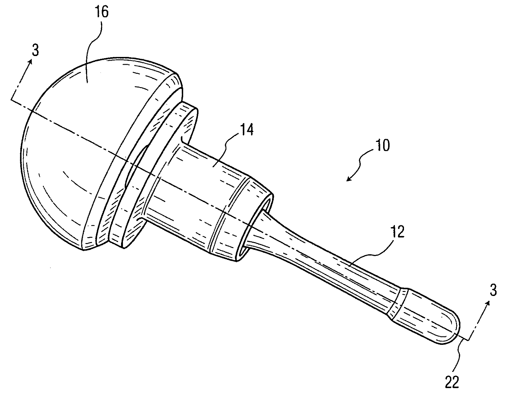
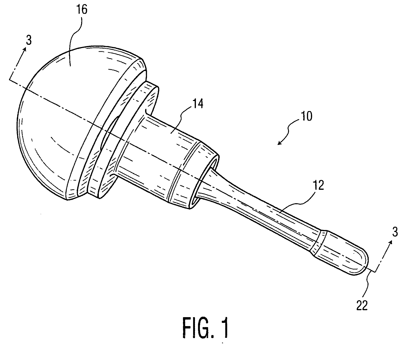
[0042]Referring to FIG. 1 there is shown a femoral head prosthesis generally denoted as 10 which comprises a shaft or intermediate solid body member 12, a sleeve 14 and a part spherical femoral prosthetic head 16. FIG. 1 shows the elements 12, 14 and 16 in an assembled configuration.

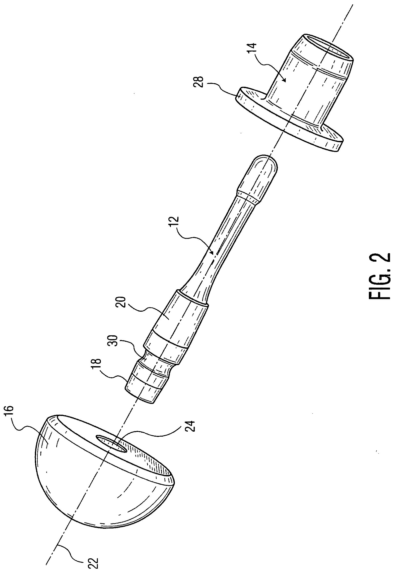
[0043]Referring to FIG. 2 there is shown an exploded view of the femoral head prosthesis of FIG. 1 with the proximal prosthetic femoral head 16 separated proximally from shaft 12 and the sleeve 14 separated distally of the shaft 12. It can be seen that shaft or intermediate solid body member 12 includes a proximal conically tapered male portion 18 and an intermediate conically tapered male portion 20. In the preferred embodiment conically tapered portion 18 is tapered towards the longitudinal axis 22 of shaft 12 while moving from a distal to proximal direction. The intermediate tapered portion 20 is tapered towards longitudinal axis 22 on moving from the proximal to distal direction.

[0044]As best seen in...


PUM


Abstract

An implant is provided for replacing the proximal portion of a femur having a substantially intact natural femoral neck and a lateral side opposite the femoral neck, with a bore extending from the femoral neck through a lateral side of the femur. The implant comprises a sleeve having a flange for engaging a proximally facing resected surface of the neck surrounding the bore in the femur and having a bore with an inwardly tapered conical portion. A shaft member having a longitudinal axis, a distal end, and a proximal end is placed in the bore through the femur. The shaft member has an intermediate conically tapered male portion for coupling to the conically tapered bore of the sleeve and a proximal end having a conically tapered portion. A head member having a distal end and a proximal substantially-spherical portion and a tapered recess is configured for positioning in a natural or prosthetic hip socket.

Description

BACKGROUND OF THE INVENTION[0001]The present application relates to an improved apparatus and method for hip replacements, and more specifically to a less-invasive prosthetic which replaces the femoral head while retaining the natural femoral neck.[0002]A widely used design for replacement of the proximal portion of a femur employs an elongate, often curved, shaft that extends into the medullary canal of the femur. This design may place unnatural stresses on the femur which lead to pain and the consequential curtailment of activity for the patient. Further, present techniques can lead to proximal bone loss and call for the resection of the majority of the femoral neck. Current designs also call for fixing the prosthesis in the proximal third of the femur. The useful life of an intramedullary implant is often less than the expected life span of a young patient.[0003]Previously known prostheses for replacing a femoral head that do not extend into the medullary canal have been mechanic...

Claims


Application Information

Patent Timeline
Patent Type & Authority Applications(United States)
IPC IPC(8): A61F2/36
CPCA61B17/742A61F2/3601A61F2002/30332A61F2220/0033A61F2002/30729A61F2002/30738A61F2002/30616
Inventor CROFFORD, THEODORESANTARELLA, MICHAEL
Owner HOWMEDICA OSTEONICS CORP
Why Eureka
Try Eureka