Pulsed plasma thruster and method of operation thereof

a pulsed plasma and thruster technology, applied in the direction of reactive propulsion thrust devices, jet propulsion plants, using plasma, etc., can solve the problems of limited discharge energy and serious edge effects in electrodes, and achieve the effect of reducing the heating effect of subsequent pulses

Inactive Publication Date: 2010-02-04
UNIV OF SOUTHAMPTON
View PDF10 Cites 5 Cited by
  • Summary
  • Abstract
  • Description
  • Claims
  • Application Information

AI Technical Summary

Benefits of technology

[0020]The subsequent pulses, after the main pulse, are accomplished, in an embodiment of the invention, by employing an extra pair of electrodes downstream. They are located downstream to reduce the heating effects of the subsequent pulses on the surface of the propellant that would otherwise cause more sublimation of propellant. The second pair of electrodes may be used as a divergent nozzle. Other discharge chamber geometries are possible, including coaxial, side-feed and others.

Problems solved by technology

US2003 / 033,797 addresses the problem of late time ablation indirectly by using a relatively high, but constant frequency discharge However, the energy of the discharge is limited due to the use of the propellant as a capacitor as well as other energy limited storage components.
It is not recommended to have a rectangular design for a QSMicro-PPT, since the edge effects in the electrodes would become a serious issue.

Method used


Image

  • Pulsed plasma thruster and method of operation thereof
  • Pulsed plasma thruster and method of operation thereof
  • Pulsed plasma thruster and method of operation thereof

Examples


Embodiment Construction

[0027]The present invention will now be described, purely by way of example, with reference to the accompanying drawings, in which:

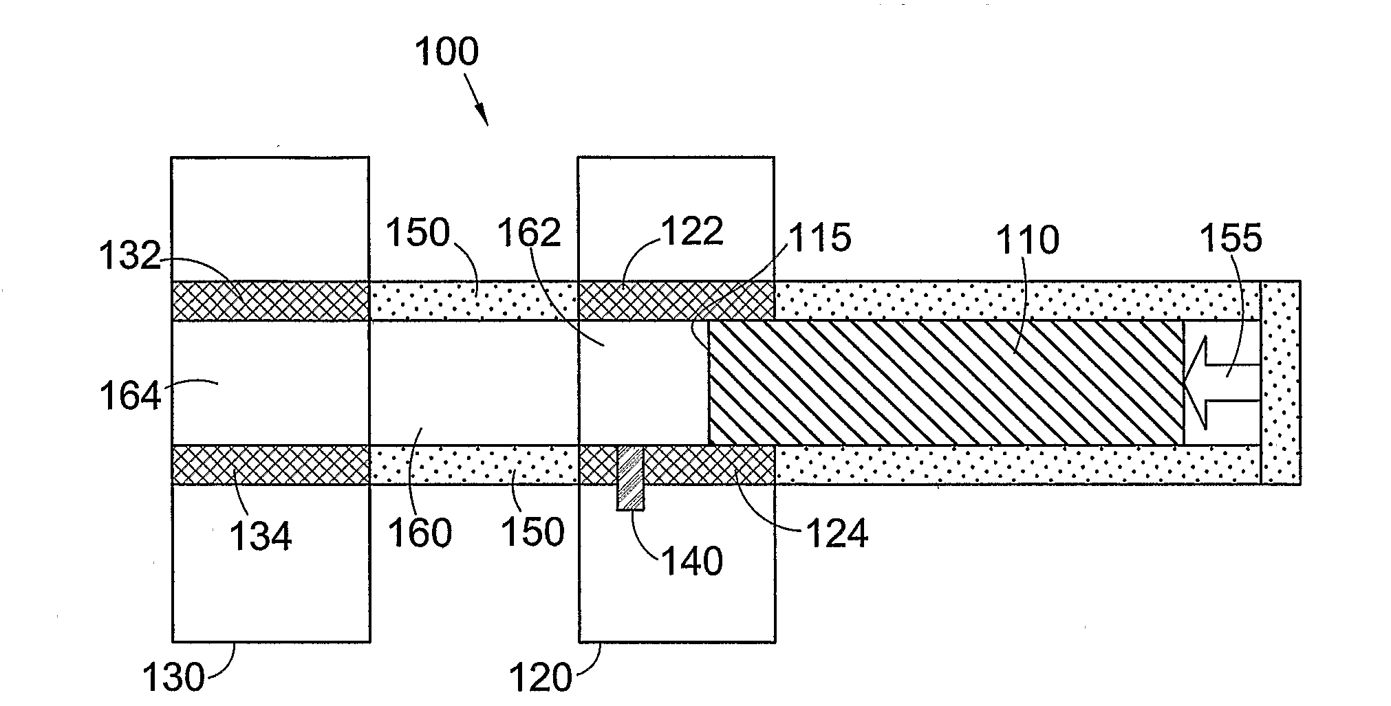
[0028]FIG. 1 shows a schematic cross section diagram of a pulsed plasma thruster according to an embodiment of the invention;

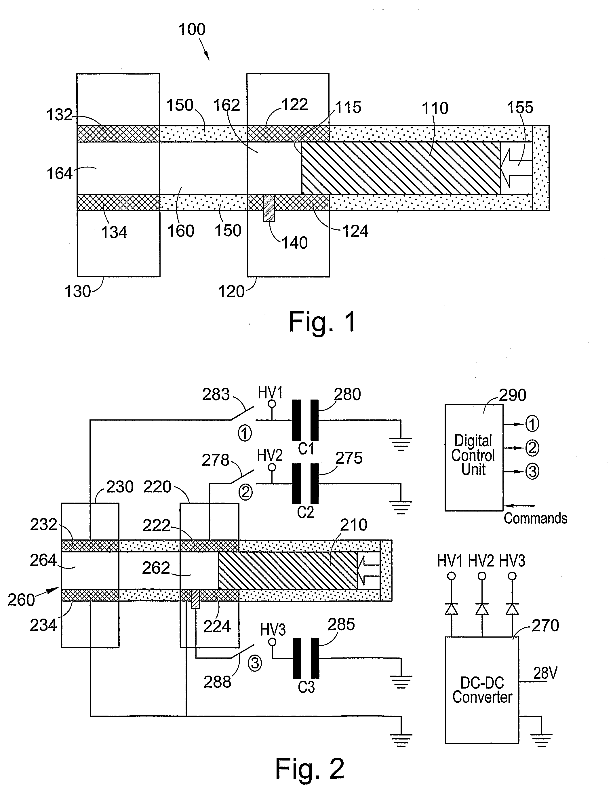
[0029]FIG. 2 shows a schematic cross section diagram of the pulsed plasma thruster of FIG. 1, with associated control circuitry;

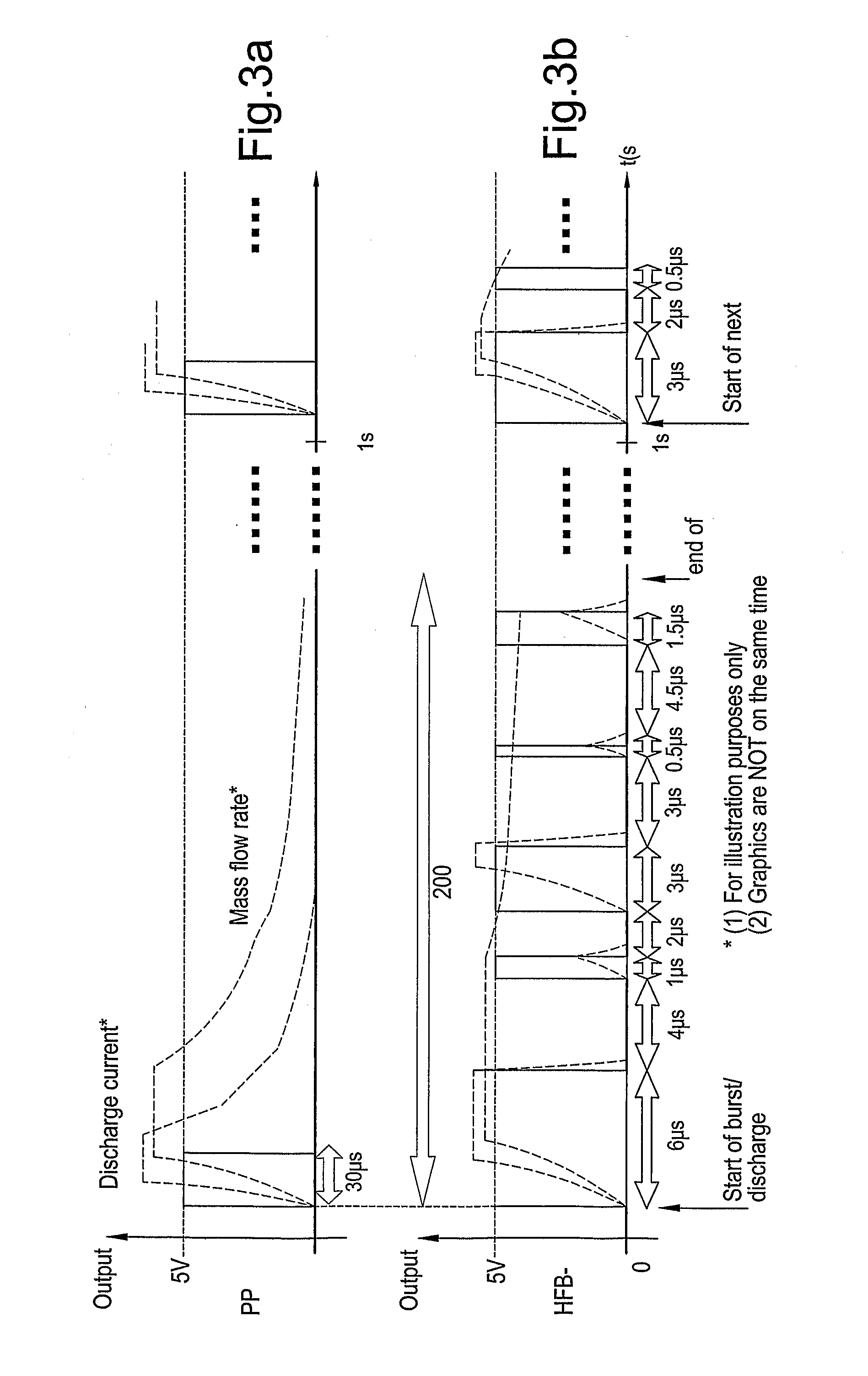
[0030]FIG. 3a shows an idealised graph of discharge control and the resultant mass flow rate against time for a conventional pulsed plasma thruster;

[0031]FIG. 3b shows an idealised graph of discharge control and the resultant mass flow rate against time for a discharge control according to an embodiment of the invention;

[0032]FIG. 4 shows a rectangular geometry thruster according to an embodiment of the invention;

[0033]FIG. 5a shows a first regime of operation of the thruster of FIG. 4;

[0034]FIG. 5b shows a second regime of operation of the thruster of FIG. 4;

[0035]FIG. 5c shows a third regime of operation...


PUM


Abstract

A pulsed plasma thruster and method of operation are provided. The pulsed plasma thruster comprises solid propellant material. A main discharge source provides a pulsed discharge across the propellant material for ablating the propellant material to produce propellant plasma and accelerating the ablated propellant plasma, and an auxiliary discharge source accelerates late ablated propellant plasma without substantially further ablating the propellant material.

Description

FIELD OF THE INVENTION[0001]The present invention relates to acceleration of sublimed material in a pulsed plasma thruster. In particular, the present invention relates to acceleration of late time ablated material from a thruster to provide thrust therefrom.BACKGROUND OF THE INVENTION[0002]A pulsed plasma thruster (PPT) is an electric thruster used for attitude control, orbit maintenance (Guman e Nathanson, 1970; Vondra e Thomassen, 1974; Vondra, 1976), orbit transfer, drag compensation, and formation flying (Ebert et al, 1989) of satellites, space probes and other space vehicles.[0003]These thrusters use a high-voltage discharge applied to the surface of a solid propellant (usually PTFE—Polytetrafluoroethylene). The propellant is sublimated, ionized and accelerated by a combination of electromagnetic forces (Lorenz Force) and thermal expansion to produce thrust.[0004]The electric discharge takes place within a discharge chamber. There are several possible geometries of discharge c...

Claims


Application Information

Patent Timeline
Patent Type & Authority Applications(United States)
IPC IPC(8): F03H1/00
CPCF03H1/0087F03H1/00
Inventor GABRIEL, STEPHEN BERNARDINTINI MARQUES, RODRIGO
Owner UNIV OF SOUTHAMPTON
Why Eureka
Try Eureka