Low emission fluid transfer device

a fluid transfer device and low emission technology, applied in the direction of pressure relieving devices on sealing faces, container discharging methods, couplings, etc., can solve the problems of inconvenient movement, and high cost of waste, so as to avoid inadvertent loss of fluid and reduce accidental movement

Active Publication Date: 2010-02-04
MARSHALL EXCELSIOR CO
View PDF38 Cites 43 Cited by
  • Summary
  • Abstract
  • Description
  • Claims
  • Application Information

AI Technical Summary

Benefits of technology

[0008]The pilot valve feature allows the actuator to move the main valve without requiring much force when the transfer device is mounted to a suitable receiver, but makes it difficult to open the main valve when the transfer device is disconnected from the receiver. For example, in one aspect of the invention, when the transfer device is mounted to the receiver and the pilot valve is moved to the open-pilot valve position, fluid is allowed to pressurize in front of and behind the main valve. This makes it easy to move the main valve to the open-main valve position and establish fluid communication. Conversely, when the transfer device is disconnected from the receiver, pressure of the fluid behind the main valve urges it into the closed position. It's not until the main valve is coupled to the receiver and pressure can be equalized in front of and behind the main valve that the operator can easily open the main valve. Pressures of about 25 to about 200 psi are often encountered, such as in liquid propane (LP) transfer.
[0010]The cam plate provides a quick acting shut-off. The cam plate configuration allows the operator to bump the actuator and rotate the actuator only a fraction of a rotation to move the valve assembly to the closed position in a quick manner. This can be extremely useful in cases where leaks occur and fluid communication must be stopped immediately to avoid fluid loss.
[0011]The present invention further provides a transfer device for coupling to a receiver. The transfer device comprises a housing defining a bore having a first end and a second end disposed along a longitudinal axis. The housing further defines a first race having a first width adjacent the second end. A valve assembly is disposed in the bore and moveable between open and closed positions. An actuator is coupled to the valve assembly for moving the valve assembly between the open and closed positions. A connector is coupled to the housing about the second end and defines a second race having a second width. A plurality of bearing members are disposed between the first race and the second race for allowing rotational movement of the connector relative to the housing about the longitudinal axis. The connector pivots between different angular positions relative to the longitudinal axis to ease mounting of the transfer device to the receiver.
[0012]Thus, the connector can both swivel (or rotate) and pivot. The swiveling and pivoting motion provides assistance to couple the transfer device to the receiver. Typically, the transfer device needs to be aligned accurately with the receiver for coupling the two together. Due to the weight of the transfer device, which is formed primarily of metal components, this can often be difficult to achieve. With a pivoting and swiveling connector coupled to the housing, the transfer device does not need to be aligned perfectly with the receiver, making installation easier.
[0014]The lock secures the actuator to the housing to hold the valve assembly in the closed position. The lock further reduces any accidental movement to move the valve assembly to the open position, avoiding inadvertent loss of fluid.

Problems solved by technology

This waste can be costly when added across hundreds to thousands of deliveries.
Emissions from some fluids can also be hazardous or damaging to the environment.
In addition to the emissions associated with de-coupling the transfer device and receiver, inadvertent emissions can also occur by accidentally opening the valve assembly prior to being ready for transfer.
Some levers or hand wheels require an excessive amount of torque to close the valve assembly and stop fluid flow during an inadvertent emission.
The extra effort and time to close the valve assemblies can result in large amounts of unnecessary fluid emissions.
The interconnection of the transfer device and the receiver in prior art systems can often be difficult for an operator.
The equipment is normally very heavy for an operator to carry and couple to the receiver simultaneously.

Method used


Image

  • Low emission fluid transfer device
  • Low emission fluid transfer device
  • Low emission fluid transfer device

Examples


Embodiment Construction

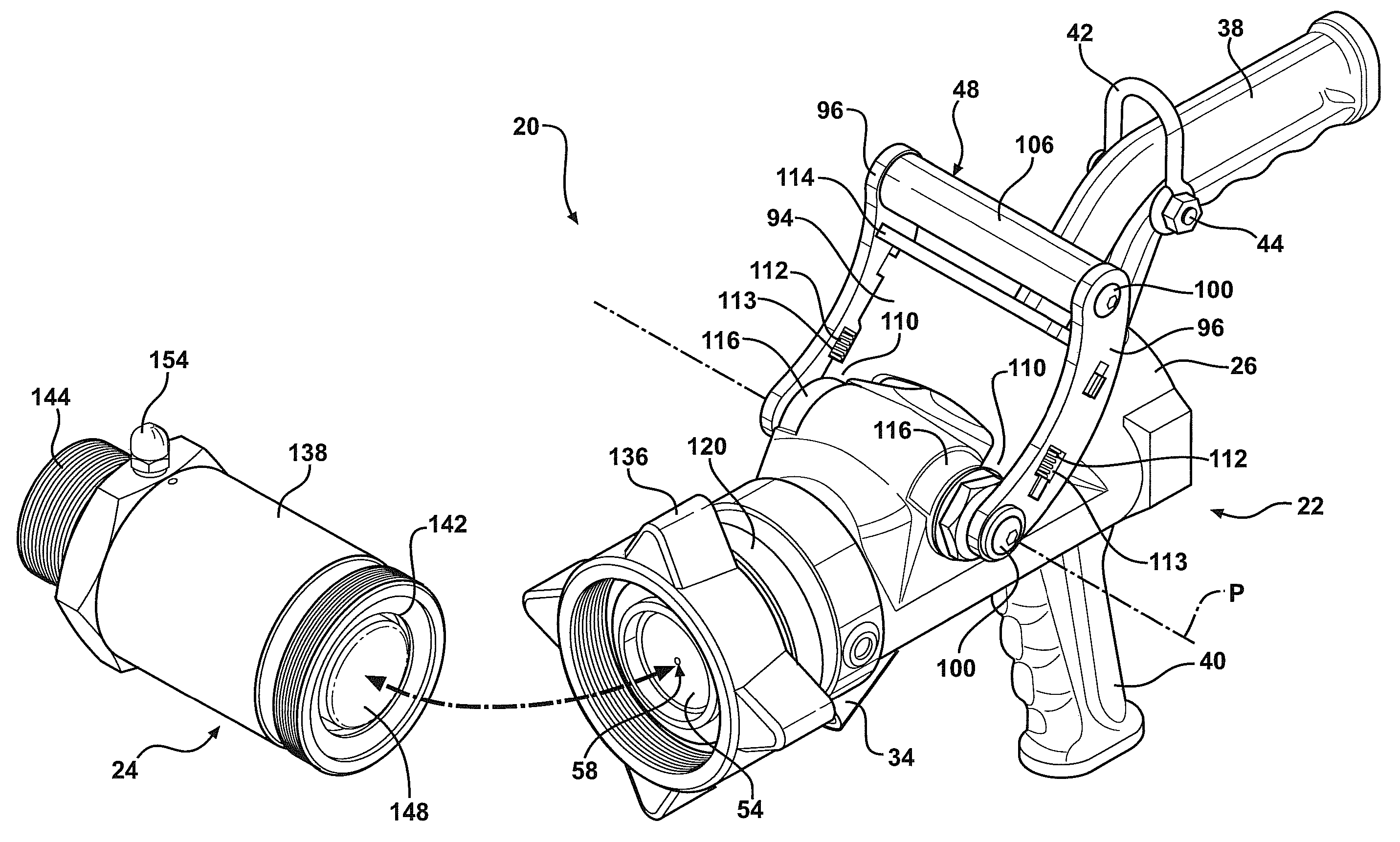
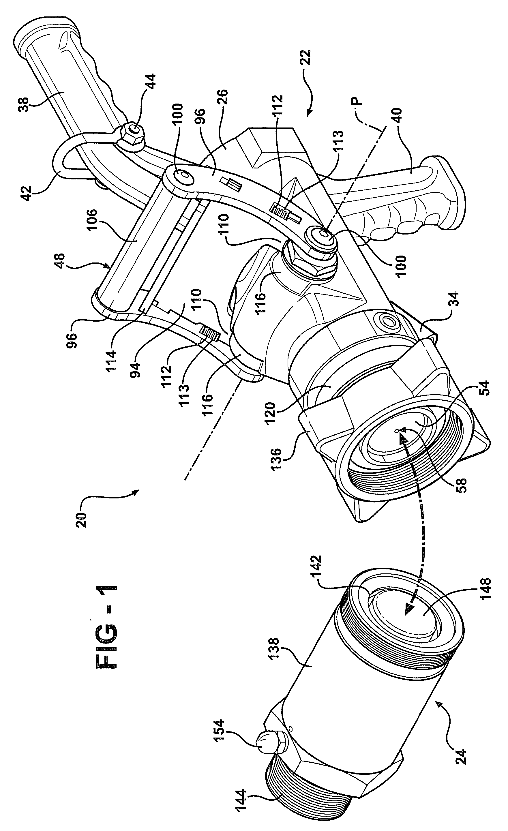
[0030]Referring to the Figures, wherein like numerals indicate like or corresponding parts throughout the several views, a fluid transfer system is generally shown at 20. Referring to FIG. 1, the fluid transfer system includes a transfer device 22 and a dry break coupler 24. Generally, the transfer device 22 is coupled to a conduit (not shown) attached to a fluid source. The dry break coupler 24 is generally coupled to a conduit (not shown) attached to a fluid destination such as a storage tank. The transfer device 22 is configured to releasably connect to the dry break coupler 24 to provide fluid communication between the fluid source and the fluid destination. The fluid travels from the fluid source to the fluid destination under a fluid pressure. The fluid can include liquid or gas. The present invention is particularly adapted for transferring liquid propane, but is not intended to be so limited.

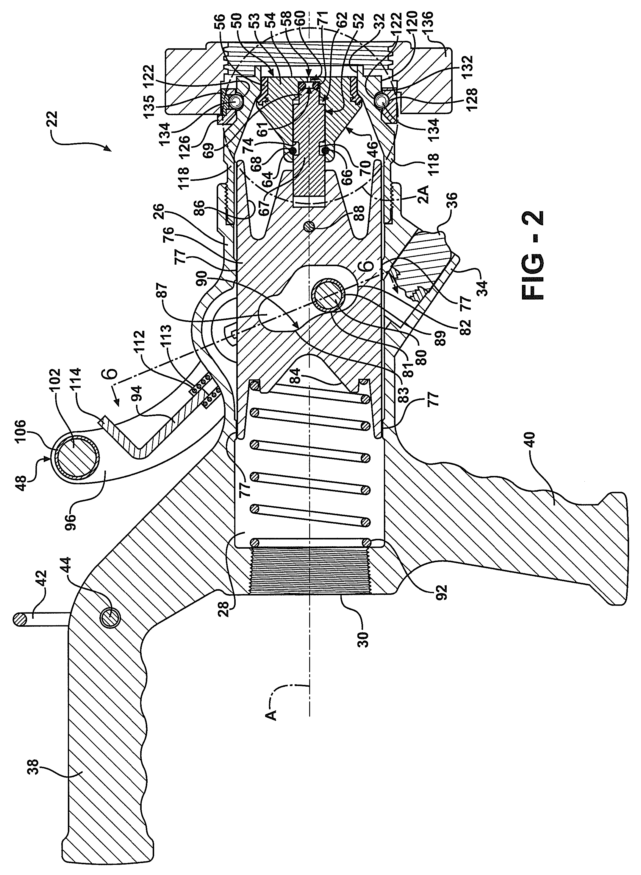
[0031]Referring to FIGS. 2 and 2A, the transfer device includes a housing 26 that de...


PUM


Abstract

A fluid transfer system includes a transfer device coupled to a dry break coupler. The transfer device includes a valve assembly moveable between an open and a closed position. The valve assembly includes a main valve and a pilot valve. An actuator controls both the main valve and the pilot valve. A cam plate interconnects the actuator and the valve assembly. The cam plate provides a quick acting shutoff to quickly move the valve assembly to the closed position. A pivotal and rotatable connector couples the transfer device to the dry break coupler. A lock is integrated with the actuator to lock the valve assembly in the closed position.

Description

FIELD OF THE INVENTION[0001]The present invention generally relates to fluid transfer systems for providing fluid communication between a fluid source and a fluid destination. More specifically, the present invention relates to a fluid transfer system including a transfer device and a dry break coupler that releasably join together to link the fluid source and the fluid destination.BACKGROUND OF THE INVENTION[0002]Fluid transfer systems are generally used for transferring fluid, e.g., gas or liquid, from a fluid source, e.g., a delivery truck, to a fluid destination, e.g., a storage tank. These fluid transfer systems often use conventional valve assemblies and conduits to communicate and manage fluid flow. Typically, a transfer device includes a valve assembly that opens to release the flow of fluid from the delivery truck. The storage tank often includes a receiver or connector to which the transfer device is releasably coupled. Once the transfer device is mounted to the receiver o...

Claims


Application Information

Patent Timeline
Patent Type & Authority Applications(United States)
IPC IPC(8): F15B15/00
CPCF17C13/04F17C2205/0376B67D7/36F17C2205/037F17C2205/0385F16L27/02F17C2223/0153F17C2223/033F17C2260/036F17C2260/044F17C2221/035Y10T137/86984Y10T137/87113Y10T137/8593Y10T137/8704Y10T137/87981Y10T137/86976Y10T137/87973Y10T137/7069Y10T137/9029F16L29/04F16L37/36F16K31/143F16K31/602F16K35/04
Inventor HOFFMAN, ALEX L.BLANCHARD, FREDERICK W.
Owner MARSHALL EXCELSIOR CO
Why Eureka
Try Eureka