
Electrical tool with gear switching

a gear switching and electric tool technology, applied in the field of electric tools, can solve the problem of a certain amount of space for adding additional components

Active Publication Date: 2010-02-04
AEG ELECTRIC TOOLS
View PDF14 Cites 18 Cited by
  • Summary
  • Abstract
  • Description
  • Claims
  • Application Information

AI Technical Summary

Benefits of technology

[0010]A solution to one or more of the above problems is provided by the features of the claimed electrical tools. According to embodiments of the present invention, the actuating element comprises a transmission means stationary with respect to the actuating elements and which is directly contactable with the corresponding coupling sleeve for actuation thereof. The transmission means is, thus, an element fixedly installed on the actuating elements and acting immediately, that is without additional diverting or guiding mechanisms, onto the coupling sleeve. In such a configuration of the actuating element, in which a transmission means comprising the above features is provided, a complicated structure of the switching slider or similar components may be dispensed with. By omitting such a component, the entire electrical tool may be constructed in a simpler manner and the housing may be made slimmer.
[0025]Preferably, the actuating element alternatively switches between a first state in which the electrical tool performs a rotational motion of the countershaft gear, and a second state in which the electrical tool performs a motion of the tumble drive, wherein the countershaft gear is rotationally fixed, and a third state in which the electrical tool performs a simultaneous motion of the countershaft gear and the tumble drive. Here, it is not necessary that the countershaft gear is rotationally fixed. In the second state, it can also rotate freely. However, it is preferred that the countershaft gear is rotationally fixed in this state.

Problems solved by technology

A disadvantage of such a configuration of an electrical tool consists in the switching slider being formed by a complex component or arrangement.
Moreover, the additional component requires a certain amount of space. in the housing and renders more complicated the manufacture of the electrical tool.

Method used


Image

  • Electrical tool with gear switching
  • Electrical tool with gear switching
  • Electrical tool with gear switching

Examples


Embodiment Construction

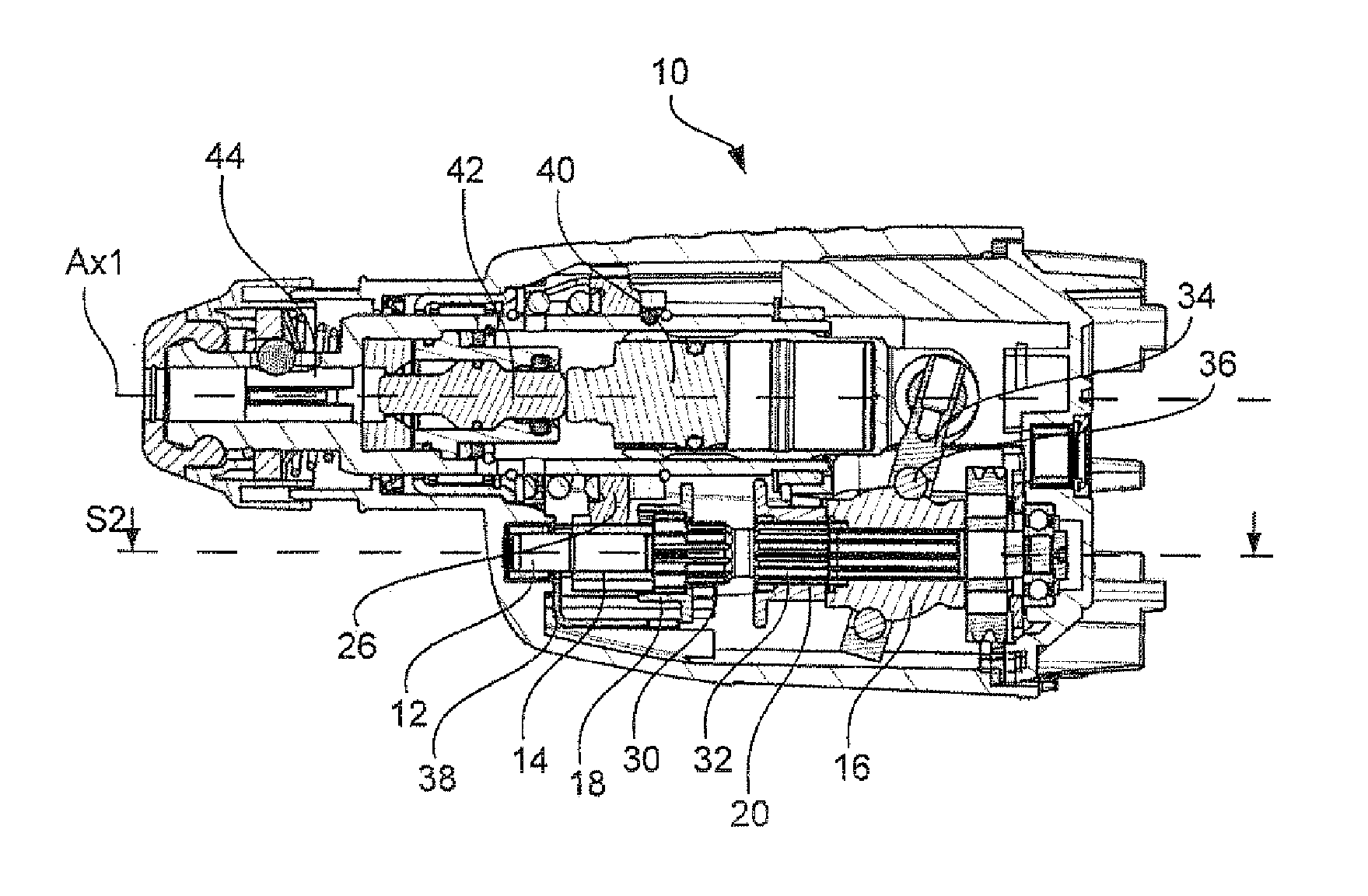
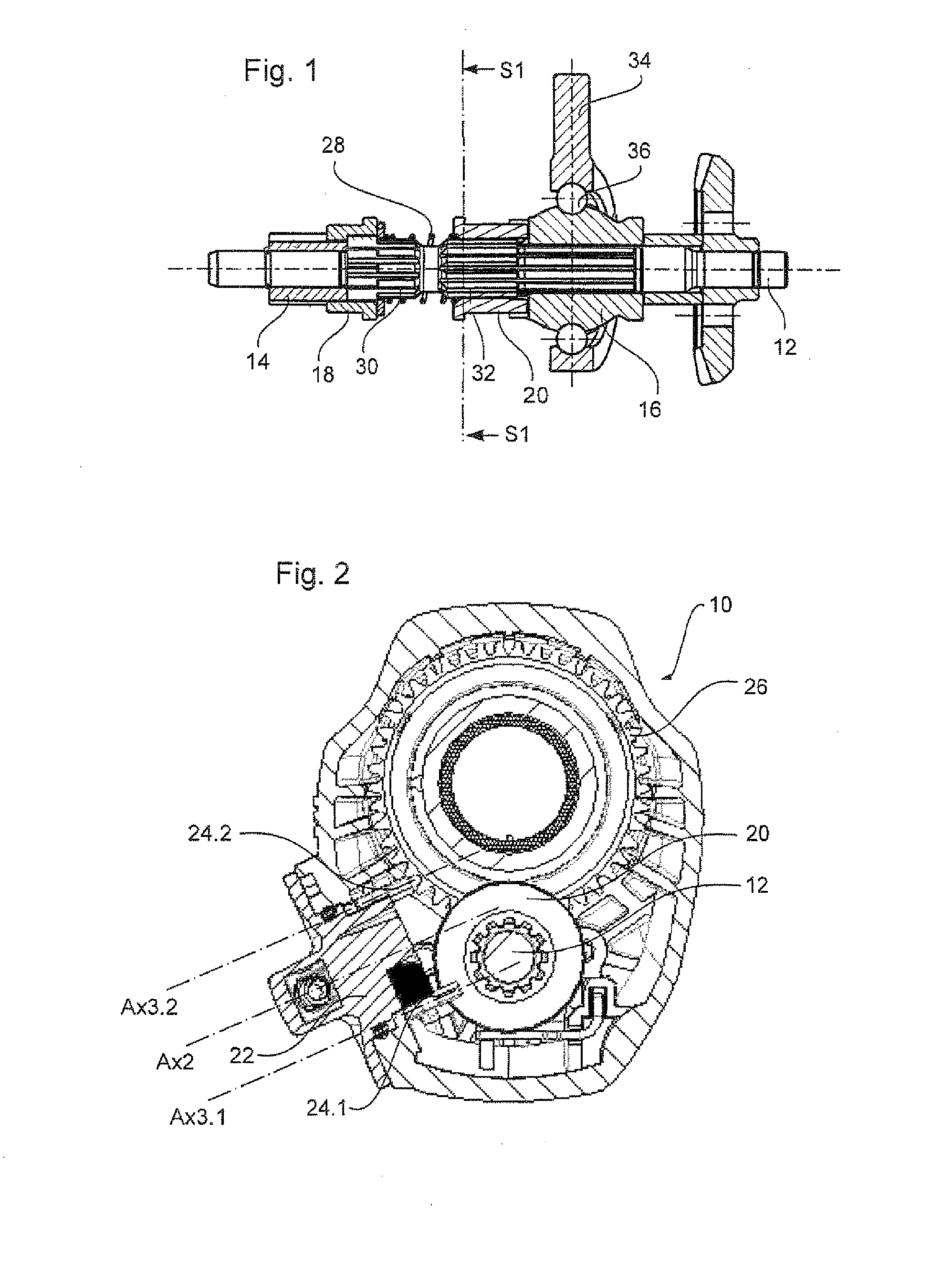
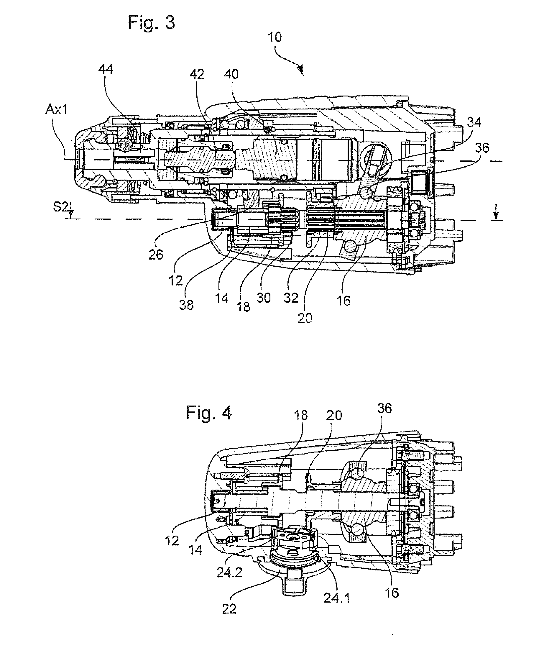
[0039]FIG. 1 shows a gear shift mechanism in a preferred embodiment of an electrical tool according to the present invention in a side sectional view. A tumble drive hub 16, a countershaft gear 14, a first coupling sleeve 18 and a second coupling sleeve 20 are free-wheelingly supported on a horizontally arranged drive shaft 12. The two coupling sleeves 18, 20 are pressed apart and into engagement with the countershaft gear 14 and the tumble drive hub 16, respectively, by means of a biasing member, such as a helical spring 28. The helical spring 28 is free-wheelingly supported on the drive shaft 12 between the two coupling sleeves 18, 20.

[0040]Thus, the spring 28 engages the coupling sleeves 18, 20 and applies a force to the sleeves 18, 20 in opposite directions. In contrast to the countershaft gear 14 and the tumble drive hub 16, the coupling sleeves 18, 20 are form-fittingly connected to the drive shaft 12 through a splined connection or pinion contour 30, 32 of the drive shaft 12....


PUM

PropertyMeasurementUnit
angleaaaaaaaaaa
spring forceaaaaaaaaaa
forceaaaaaaaaaa

Abstract

An electrical tool, in particular drill and chiselling hammer, including a drive shaft and two driven members. The drive shaft is operatively connectable with the driven members by a respective one of a pair of coupling sleeves. The coupling sleeves are actuatable by a rotatable and mechanical actuating element, in particular a mechanical rotary switch. The actuating element of the electrical tool includes a transmission means or a transmission portion that is stationary with respect to the actuating element and which is contactable directly with the respective coupling sleeve for actuating the coupling sleeves.

Description

RELATED APPLICATIONS[0001]This application claims priority to European Patent Application No. EP-08 161 170.9, filed Jul. 25, 2008, entitled ELECTRICAL TOOL WITH GEAR SWITCHING, the entirety of which is incorporated by reference herein.BACKGROUND OF THE INVENTION[0002]1. Field of the Invention[0003]The invention is directed towards an electrical tool, in particular a drill and chipping hammer having a drive shaft and two driven members, wherein the drive shaft can be operatively connected with the individual driven members by means of a coupling sleeve. The coupling sleeve can be operated by a mechanical actuating element, in particular by a mechanical rotary switch.[0004]2. Description of the Related Art[0005]Electrical tools, such as drill and chipping hammers, in which a motion of the drive shaft is transmitted to driven members are mostly provided with a coupling device that enables coupling and decoupling between the drive shaft and the driven members in order to transmit power...

Claims


Application Information

Patent Timeline
Patent Type & Authority Applications(United States)
IPC IPC(8): B23B45/02B23B45/16
CPCB25D16/006B25D2211/061B25D2216/0046B25D2216/0023B25D2216/0038B25D2216/0015
Inventor FELGER, REINER
Owner AEG ELECTRIC TOOLS
Features
  • Generate Ideas
  • Intellectual Property
  • Life Sciences
  • Materials
  • Tech Scout
  • Unparalleled Data Quality
  • Higher Quality Content
  • 60% Fewer Hallucinations
Learn More