Platelet-rich plasma separator and platelet-rich plasma separation method

Active Publication Date: 2010-02-04
NIPRO CORP
View PDF5 Cites 14 Cited by
  • Summary
  • Abstract
  • Description
  • Claims
  • Application Information

AI Technical Summary

Benefits of technology

[0043]According to the platelet-rich plasma separator and the platelet-rich plasma separation method according to the present invention, platelet-rich plasma can be obtained by centrifuging the syringe used for blood collection. Thereby separation of platele

Problems solved by technology

However, there is a problem that if a container with a rubber plug, such as the vacuum blood collection tube described in Patent Publication 1, is sterilized by gamma radiation, the rubber plug gets

Method used


Image

  • Platelet-rich plasma separator and platelet-rich plasma separation method
  • Platelet-rich plasma separator and platelet-rich plasma separation method
  • Platelet-rich plasma separator and platelet-rich plasma separation method

Examples


Example

First Embodiment

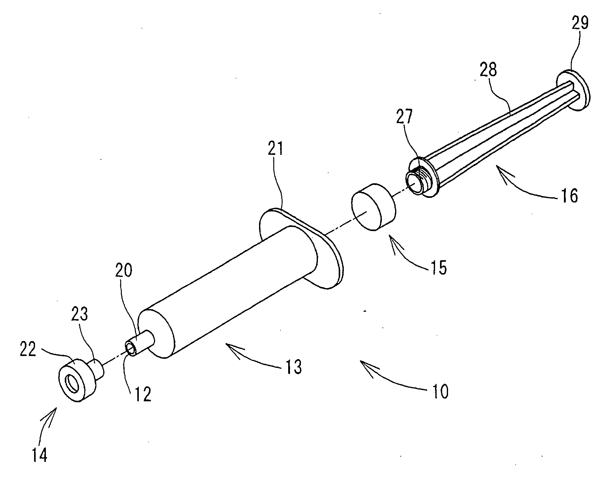
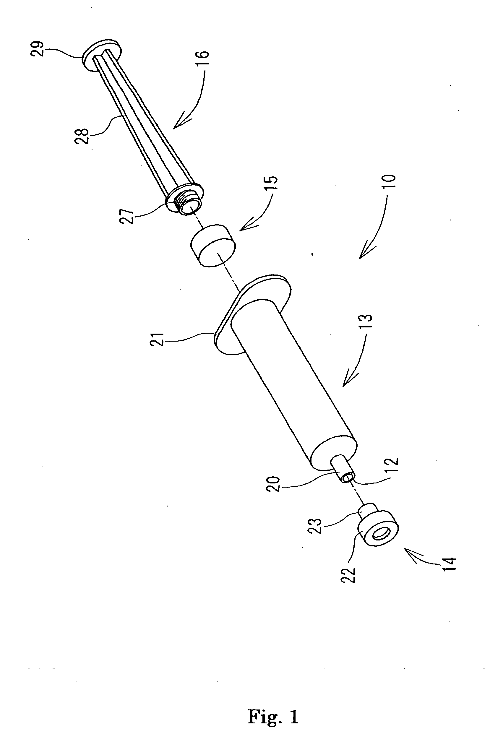
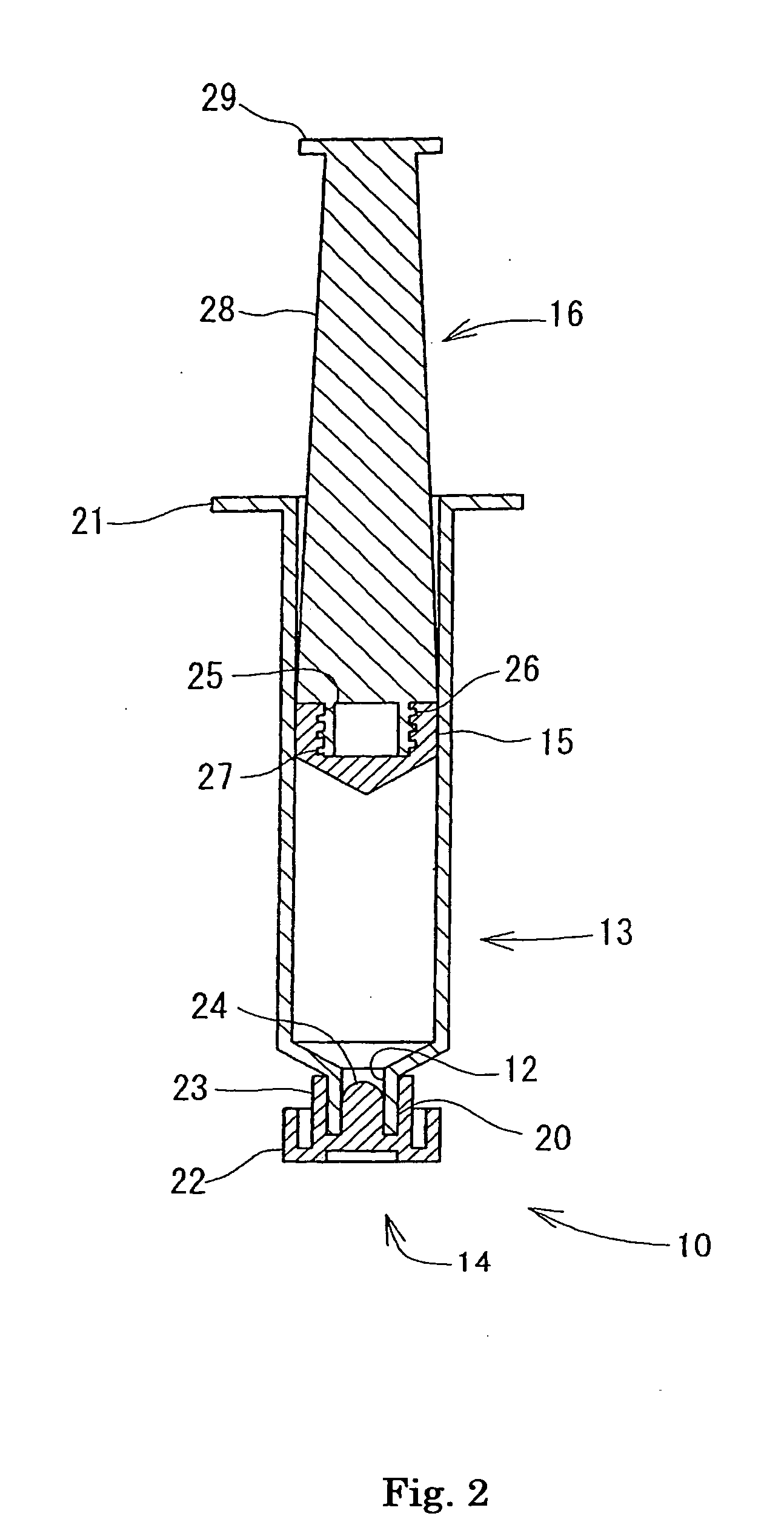
[0090]FIG. 1 is an exploded perspective view showing the external configuration of the first syringe 10 of the platelet-rich plasma separator according to the first embodiment of the invention. FIG. 2 is a longitudinal sectional view showing the internal configuration of the first syringe 10. FIG. 3 is an exploded perspective view showing the external configuration of the second syringe 11 of the platelet-rich plasma separator according to the first embodiment of the invention. FIG. 4 is a longitudinal sectional view showing the internal configuration of the second syringe 11.

[0091]The platelet-rich plasma separator according to the present invention comprises a first syringe 10 and a second syringe 11. The first syringe 10 is used in order to aspirate blood. Suction of blood is exemplified, in particular, by blood collection but not limited thereto, and includes the suction of the blood which has already been collected. The second syringe 11 is used in order to aspi...

Example

Second Embodiment

[0133]FIG. 8 is an exploded perspective view showing the external configuration of the third syringe 60 of the platelet-rich plasma separator according to the second embodiment of the present invention. FIG. 9 is a longitudinal sectional view showing the internal configuration of the third syringe 60. FIG. 10 is an exploded perspective view showing the external configuration of the fourth syringe 61 of the platelet-rich plasma separator according to the second embodiment of the present invention. FIG. 11 is a longitudinal sectional view showing the internal configuration of the fourth syringe 61.

[0134]The platelet-rich plasma separator according to the present invention comprises a third syringe 60 and a fourth syringe 61. The third syringe 60 is used in order to aspirate blood. Suction of blood is exemplified, in particular, by blood collection but not limited thereto, and includes the suction of the blood which has already been collected. The fourth syringe 61 is ...


PUM


Abstract

Provided is a platelet-rich plasma separator which can carry out the separation of a platelet-rich plasma with a small number of gamma radiation sterilized instruments and a platelet-rich plasma separation method. The platelet-rich plasma separator comprises a first syringe and a second syringe. The first syringe comprises a first syringe cylinder provided with a first port on which a blood collection needle can be mounted, a first cap detachable from the first port, a first gasket for sealing the first syringe cylinder fluid-tightly, which first gasket is reciprocated within the first syringe cylinder, and a first plunger provided detachably on the first gasket. The second syringe comprises a first hollow needle, which can be passed through the first gasket, a second syringe cylinder having a second port on which the first hollow needle can be mounted, a second cap detachable from the second port, a second gasket for sealing the second syringe cylinder liquid-tightly, which second gasket is reciprocated within the second syringe cylinder, and a second plunger provided detachable on the second gasket.

Description

TECHNICAL FIELD[0001]The present invention relates to a platelet-rich plasma separator having a syringe used to aspirate blood and a syringe used to aspirate a centrifuged section containing platelets and plasma from the syringe and to a platelet-rich plasma separation method.BACKGROUND ART[0002]Platelet-rich plasma (hereafter also referred to as “PRP”) is plasma containing a large number of platelets. Whole blood, which contains corpuscle components, contains approximately 95% red blood cells, 3% white blood cells, and approximately 1% platelets. On the other hand, platelet-rich plasma contains a higher proportion of platelets. There is no specific definition of the proportion of platelets in PRP. Taking into consideration that the proportion of plasma in whole blood is, in general, approximately 55%, the proportion of platelets in plasma from which the corpuscle components have been removed is assumed to be approximately 2%. PRP contains a clearly higher proportion of platelets th...

Claims


Application Information

Patent Timeline
IPC IPC(8): B01D21/26A61K35/14A61K35/16A61K35/19A61M1/02A61P1/02A61P17/02A61P43/00
CPCA61B5/1416A61K35/16A61M1/029A61M2202/0427A61M2005/3104A61M2005/3106A61M2005/31598A61M5/31511A61B5/15003A61B5/150236A61B5/150244A61B5/150335A61B5/150351A61B5/150389A61B5/150503A61B5/150755A61B5/1535A61P1/02A61P17/02A61P43/00
Inventor MORIMOTO, SHINJISASAYAMA, NORIHISASHIRASU, AKIO
Owner NIPRO CORP
Why Eureka
Try Eureka