
Fluid flush device with optional telescopic wand

a flushing device and telescopic wand technology, applied in the direction of spraying nozzles, liquid spraying apparatus, spraying apparatus, etc., can solve the problems of insufficient fluid spray coverage area, inability to thoroughly clean the underside of a vehicle or such other object, and limited other uses, so as to prevent unnecessary repairs, inhibit corrosion, and facilitate cleaning.

Inactive Publication Date: 2010-02-04
ELLENBECKER JEFFREY DALE
View PDF13 Cites 8 Cited by
  • Summary
  • Abstract
  • Description
  • Claims
  • Application Information

AI Technical Summary

Benefits of technology

[0018]It is an object of the present invention to provide improved elements and arrangements thereof for the purpose described which is inexpensive, dependable and fully effective in accomplishing its intended, multiple purposes, and to be universal for each and every user.

Problems solved by technology

With the use of only traditional garden hoses or a straight wand, it is awkward to thoroughly clean the underside of a vehicle or such other object.
Many devices have been developed to clean the underbody of an automobile but they are limited for many other uses.
Less complicated devices have a limited fluid spray area or a limited number of orifices rendering the fluid spray coverage area inadequate.
Such devices pose problems as well.
Although this device allows a user to stand upright, the device is 6.5 feet in length and is comprised of an integral, one piece tube without a flow-control trigger to control the water flow also limiting the users due to its length.
Being a one piece tube at 6.5 feet in length does not make it compatible or as universal as it should be to fit the everyday user's needs and sizes.
Merritt also states that the device is to be used with an ordinary garden hose which also limits the amount of users because of the amount of pressure or velocity that can be used for different circumstances.
U.S. Pat. No. 6,755,361 to Danielson et al describes an adjustable spray apparatus at the spray end, which has limited spray area due to the limited amount of orifices rendering the spray coverage area problematical for the undercarriage.
With this device not being universal, it poses a problem due to limitations.
In FIG. 4 of Danielson et al, motion C shows the handle upside down, which poses difficulties to the user seeing that the handle and trigger is actually upside down.
Even if equipped with a swivel (as mentioned) to adjust the swivel and the spray apparatus, this configuration just complicates things more to the average user with all these moving parts.
U.S. Pat. No. 4,580,726 to Unger also has caster wheels which could pose problems used anywhere else but on a flat concrete surface.

Method used


Image

  • Fluid flush device with optional telescopic wand
  • Fluid flush device with optional telescopic wand
  • Fluid flush device with optional telescopic wand

Examples


Embodiment Construction

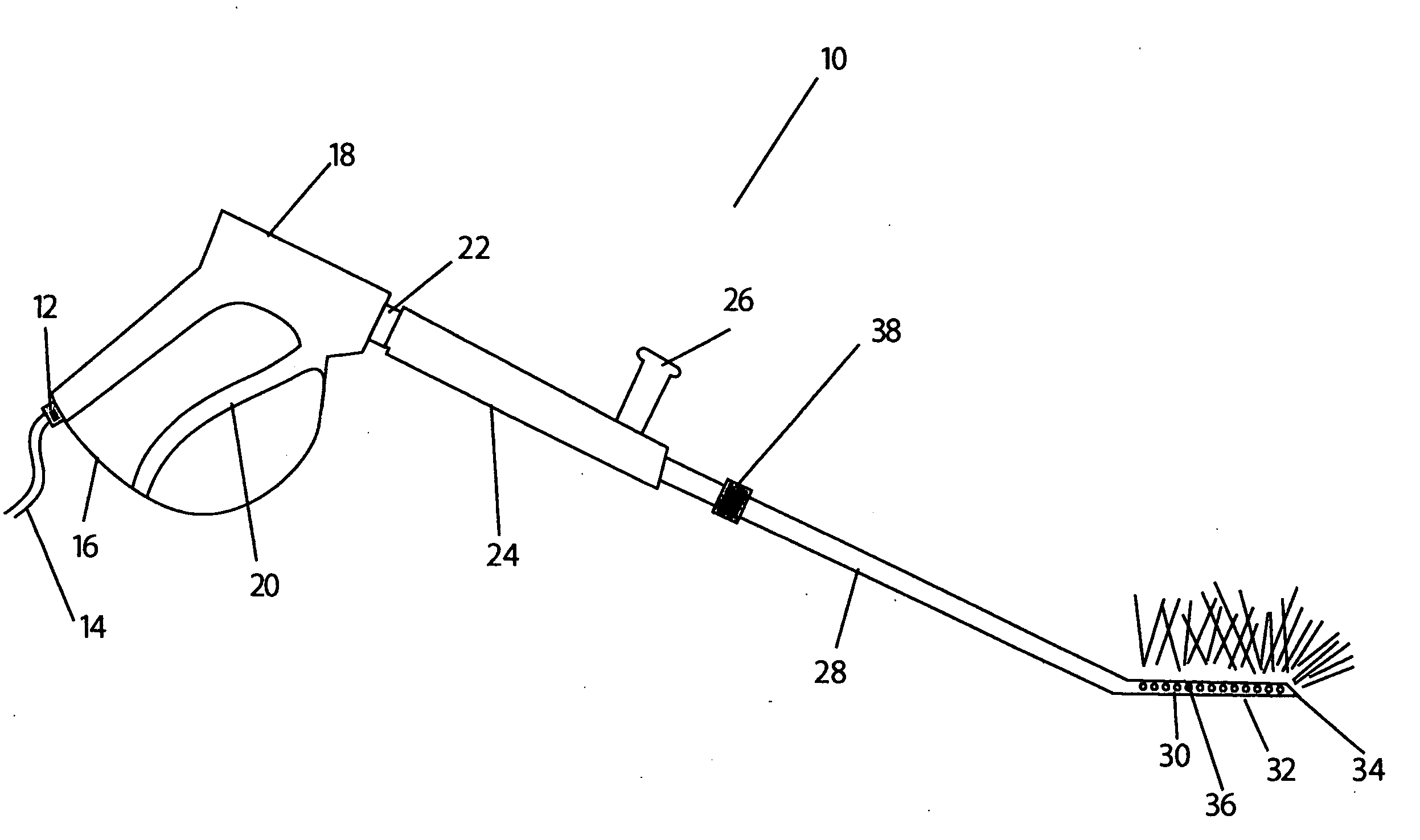
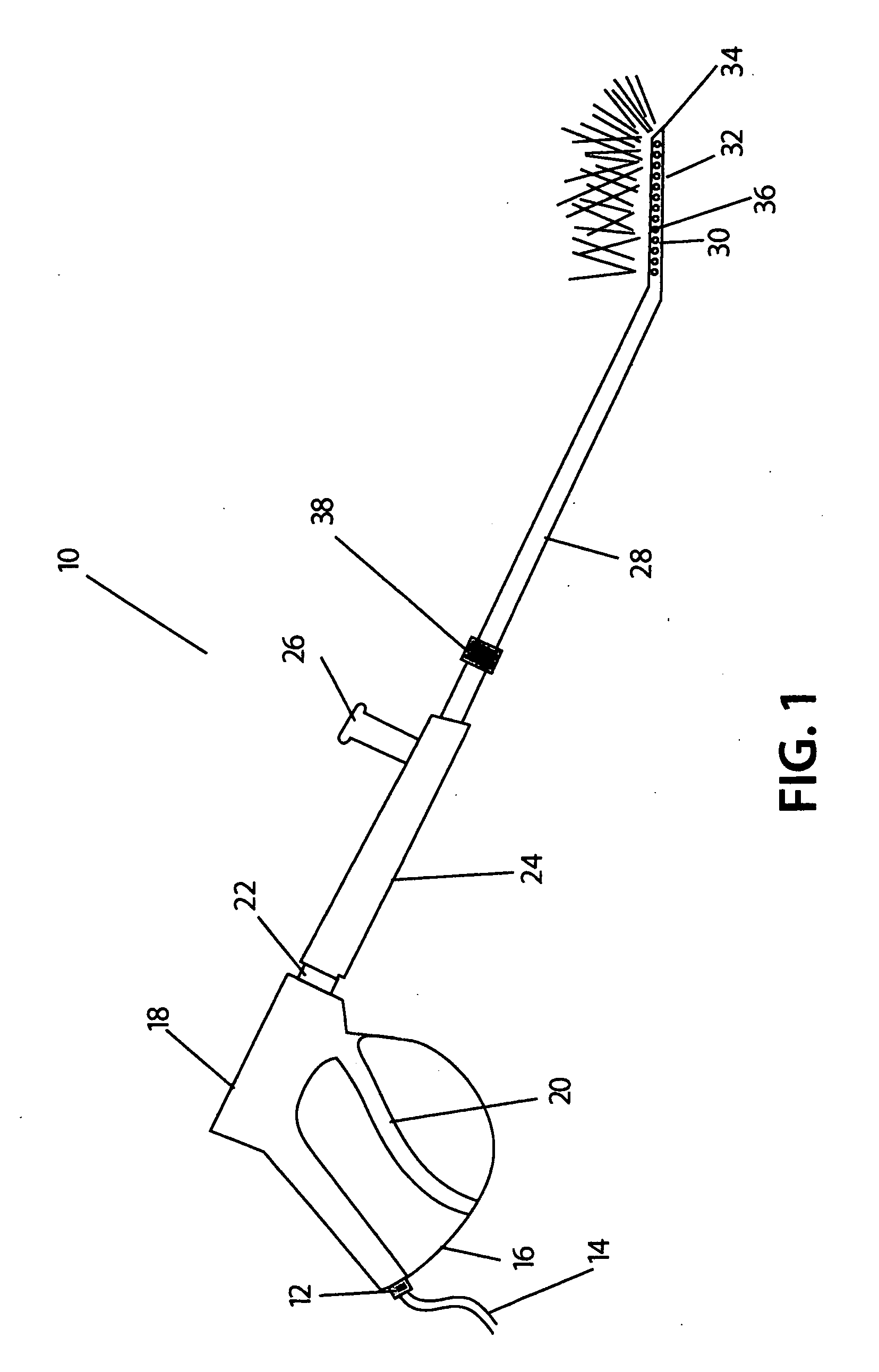
[0031]The present invention is shown in FIGS. 1 through 9. The underbody water flush or under wash of any surface or object that the user chooses with optional telescopic wand is designated generally as 10. As shown in FIG. 1, the present invention 10 comprises of a water or chemical source or alike 14 that connects to the handle 18 using a universal fitting 12. The handle 18 also consists of a flow-control trigger 20, a trigger hold 16 for constant pressure, and fittings for the wand 22. Once the wand 28 connects to the handle 18 using the fitting 22, there is an insulator 24 and optional grip 26. From here, there is also an option for a telescopic wand 38 that leads to a longitudinally pitched end 32. Defined within the end 32 there are many orifices 30 that have nozzles 36 to fit into those orifices 30 for maximum spray coverage. At the pitched end 32 there is an angled nozzle assembly 34.

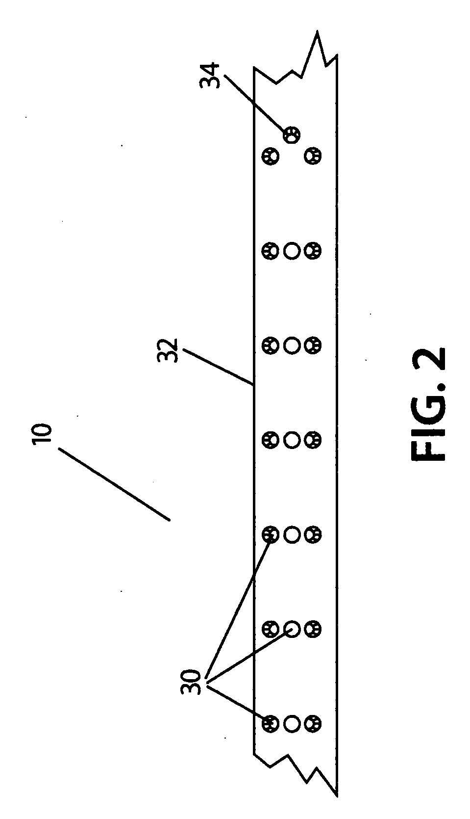
[0032]In FIG. 2, it will be seen that the pitched end 32 consist of orifices 30 and an angle...


PUM


Abstract

One embodiment of a universal fitting or fittings connected to a handle which can be made up of various materials with a flow control trigger and trigger lock or hold. The wand and insulator with optional grip can also be made up of many and different materials, which leads to an optional telescopic wand and a longitudinally pitched end having a plurality of nozzles and other nozzle assemblies.

Description

FEDERALLY SPONSORED RESEARCH[0001]Not ApplicableSEQUENCE LISTING OR PROGRAM[0002]Not ApplicableBACKGROUND [0003]1. Field of the Invention[0004]The present invention relates generally to spray cleaning devices. More particularly, it relates to a device for flushing and cleaning the under part of any surface or object that the user chooses using a fluid.[0005]2. Prior Art[0006]Any discussion of the prior art through-out the specification should in no way be considered as an admission that such prior art is widely known or forms part of common general knowledge in the field.[0007]There are many devices that utilize water or other fluids to clean or rinse deposits such as salt and dirt from the under carriage of a vehicle that pose difficulties.[0008]With the use of only traditional garden hoses or a straight wand, it is awkward to thoroughly clean the underside of a vehicle or such other object. Many devices have been developed to clean the underbody of an automobile but they are limit...

Claims


Application Information

Patent Timeline
Patent Type & Authority Applications(United States)
IPC IPC(8): B05B9/01
CPCB05B1/202B05B9/01B05B13/06B05B15/069B05B15/066B05B15/068B05B15/064B05B15/628B05B15/652B05B15/656B05B15/658
Inventor ELLENBECKER, JEFFREY DALE
Owner ELLENBECKER JEFFREY DALE
Learn More