Buck converter with surge protection

a converter and surge protection technology, applied in the direction of power conversion systems, instruments, process and machine control, etc., can solve the problems of too many components and drawbacks of conventional switching regulators, and achieve the effect of avoiding complex architectur

Inactive Publication Date: 2010-02-04
WANG SHIH YUAN
View PDF5 Cites 13 Cited by
  • Summary
  • Abstract
  • Description
  • Claims
  • Application Information

AI Technical Summary

Benefits of technology

[0008]The present invention provides a buck converter with surge protection to resolve the foregoing problems fac...

Problems solved by technology

However, conventional switching regulator has some drawback...

Method used


Image

  • Buck converter with surge protection
  • Buck converter with surge protection

Examples


Embodiment Construction

[0021]The present invention will now be described more specifically with reference to the following embodiments. It is to be noted that the following descriptions of preferred embodiments of this invention are presented herein for the purpose of illustration and description only. It is not intended to be exhaustive or to be limited to the precise form disclosed.

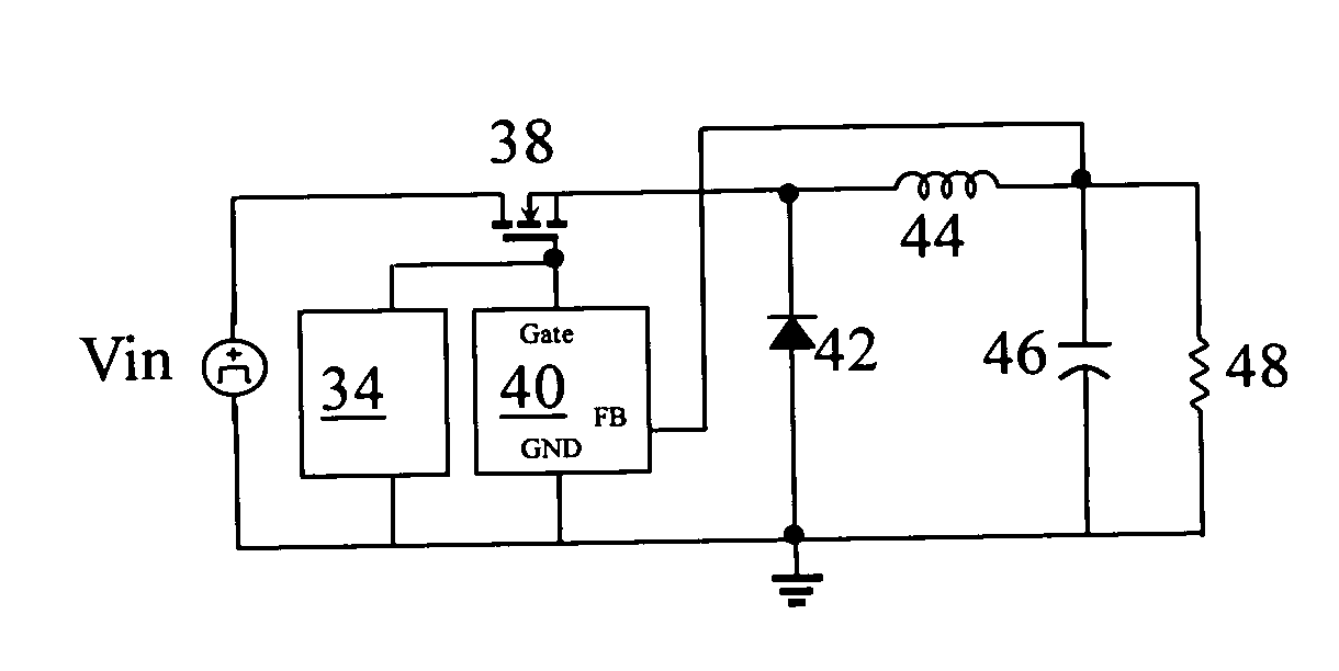
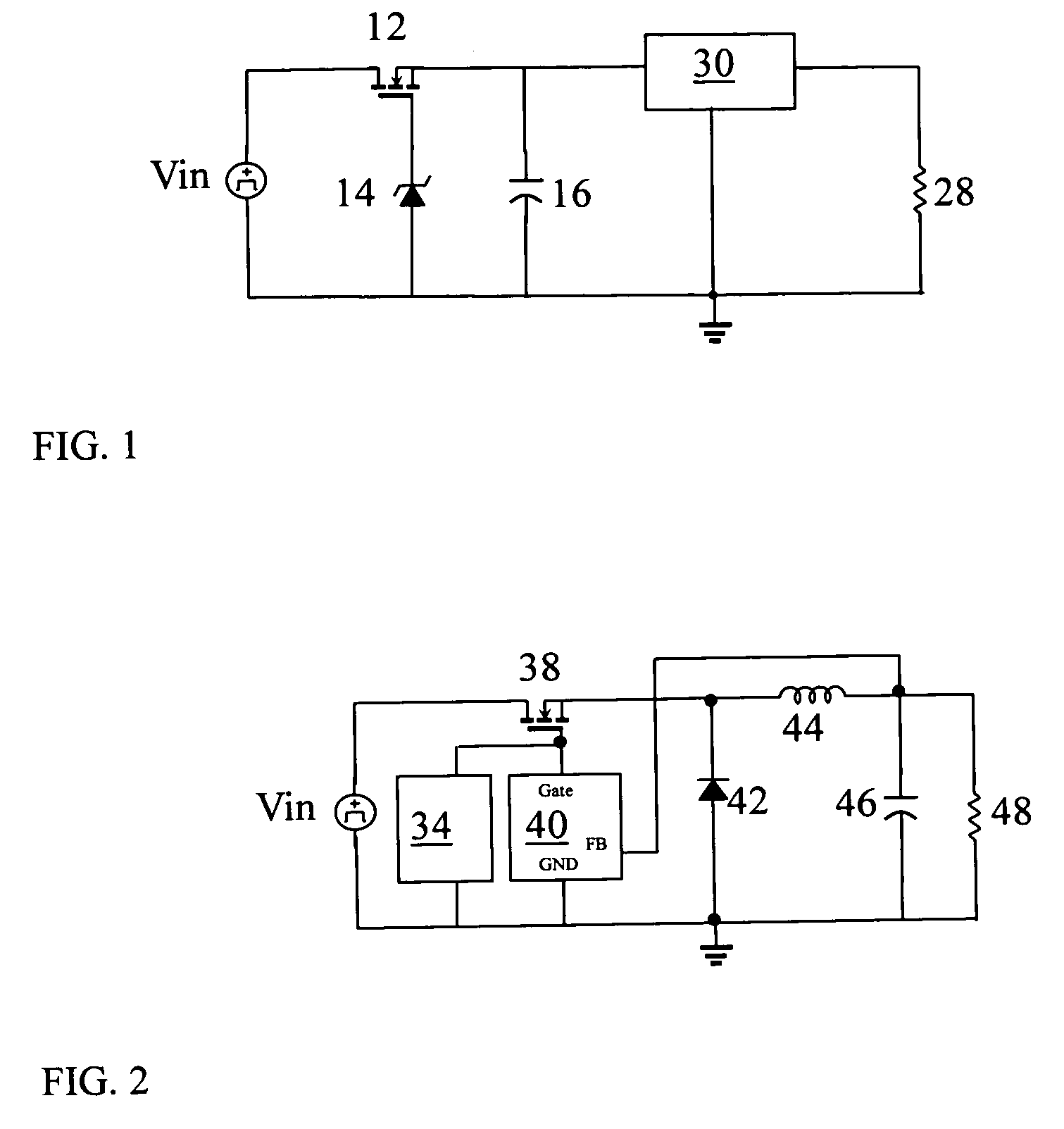
[0022]Referring to FIG. 2, a schematic diagram of a buck converter with surge protection of the first preferred embodiment according to the present invention is shown. The buck converter with surge protection includes a voltage clamp circuit 34, a NMOS 38, a control circuit 40, a rectifier diode 42, an inductor 44, an output capacitor 46 and a resistor 48.

[0023]The DC power supply Vin has its positive terminal connected to a drain terminal of the NMOS 38 and has its negative terminal grounded. The voltage clamp circuit 34 has a Zener diode. The Zener diode limits the gate-to-source voltage of the NMOS 38 below the VGS(max). T...


PUM


Abstract

A buck converter with surge protection comprises a transistor, a voltage clamp circuit, a control circuit, a rectifier diode, an inductor, an output capacitor and a resistor. The transistor is coupled to a input voltage. The voltage clamp circuit has a Zener diode. The Zener diode is coupled to the transistor for limiting gate-to-source voltage of the transistor. The control circuit is used for maintaining a constant output voltage independently of variance of the input voltage. The rectifier diode is used for commutating current maintained by the electromotive force generating at both terminals of the inductor. The inductor is used for storing energy according to the current flowing from the input voltage via the transistor. The output capacitor is used for smoothing a voltage of the inductor. The resistor is applied the smoothed voltage. Hence, the present invention may protect the high-performance power supply from the automotive over-voltage events.

Description

BACKGROUND OF THE INVENTION[0001]1. Field of the Invention[0002]The present invention relates generally to a surge protection device (SPD), and more particularly to a buck converter with surge protection that protects the high-performance power supply from the automotive over-voltage events.[0003]2. Description of Prior Art[0004]Conventional switching regulators regulate voltage and block automotive load-dump pulses.[0005]Referring to FIG. 1, a schematic diagram of a conventional switching regulator is shown. The switching regulator includes a n-channel MOSFET 12, a Zener diode 14, a load 16, a resistor 28 and a DC-DC converter 30.[0006]The DC power supply Vin has its positive terminal connected to the drain terminal of the n-channel MOSFET 12 and has its negative terminal grounded. The Zener diode 14 limits the gate-to-source voltage of the n-channel MOSFET 12 below the VGS(max). The n-channel MOSFET 12 operates in saturation when the input voltage Vin is below the breakdown voltag...

Claims


Application Information

Patent Timeline
IPC IPC(8): G05F1/571
CPCH02M1/32
Inventor WANG, SHIH-YUAN
Owner WANG SHIH YUAN
Why Eureka
Try Eureka