Impedance-based arc fault determination device (IADD) and method

a fault determination device and arc technology, applied in short-circuit testing, impedence measurement, instruments, etc., can solve problems such as voltage variation, rms voltage change, and difficulty in defining these values from an intrinsic sense, so as to accurately determine the real-time load and accurately estimate the fault duty

Active Publication Date: 2010-02-04
CLEMSON UNIV RES FOUND +1
View PDF12 Cites 16 Cited by
  • Summary
  • Abstract
  • Description
  • Claims
  • Application Information

AI Technical Summary

Benefits of technology

[0031]Provided herein are embodiments of a device and method that can accurately and correctly predict the expected bolted fault current at the test location of interest. Embodiments of the device and method apply a known load and measure the change in RMS and instantaneous voltage due to the step increase in loading conditions and the phase shift in the voltage waveform as a result of the change in loading conditions at the test node. Subsequently, the load current is measured to more accurately determine the real time load imposed upon the system. With knowledge of the load impedance, an accurate equivalent Thevenin or Norton system along with resistive and reactive parameters and X / R ratio can be derived through a series of mathematical calculations. Then, using the derived equivalent circuit, an accurate estimate of the fault duty can be obtained.

Problems solved by technology

Defining these values from an intrinsic sense can be challenging.
A significant source of voltage variation is the constant changes in loading conditions, particularly large load changes such as motor starting that may cause momentary changes in the RMS voltage.
However, increases in loading cause increases in voltage drop.
It is undesirable to cause a voltage drop (a so-called voltage “dip” or “sag”) deep enough that either equipment in the facility misoperates or that an undesired power system dynamic results.
The resistive load, however, changes both the magnitude and phase angle of the resultant phasor significantly.
There are some challenges with using a capacitive load due to the potential for exciting resonances between capacitance and natural inductance present in the system.
Overvoltages may cause measurement error due to A / D saturation, can pose threats to the test equipment as it is rated for 600 Vrms as well as for the system itself under certain conditions.
Since most electrical power system equivalents are dominated with inductive reactance, using a purely inductive load will also be problematic.
Although the voltage drop magnitude can be significantly affected, since the drop is closely in-phase with system impedance the changes in phase shift during testing are likely to be small.
However, due to slight differences in sampling frequency with respect to the 60 Hz input waveform, there is some drift noted from cycle to cycle.
The card can sample with, for example, 14 bit accuracy, so there is some quantization error associated with the RMS measurements.
Conversely, weak systems are typically resistive due to the fact that low voltage feeder impedance is typically resistance dominated.
Unfortunately, as discussed above, a small drop in voltage on a system with high X / R ratio typically requires drawing significant current due to system stiffness.
Additional error can be introduced into calculated phase shift calculated due to the physical construction of the IADD.
This shift results in skewed voltage measurements that can cause additional error in the phase shift calculations.
It was noted that, when the IADD neutral is not solidly bonded to the power system's system neutral, unbalanced shifts in phase angle were observed.
Case 34D, however, would result in an error in measured phase shift by approximately 6% under the loading conditions shown.

Method used


Image

  • Impedance-based arc fault determination device (IADD) and method
  • Impedance-based arc fault determination device (IADD) and method
  • Impedance-based arc fault determination device (IADD) and method

Examples


example 1

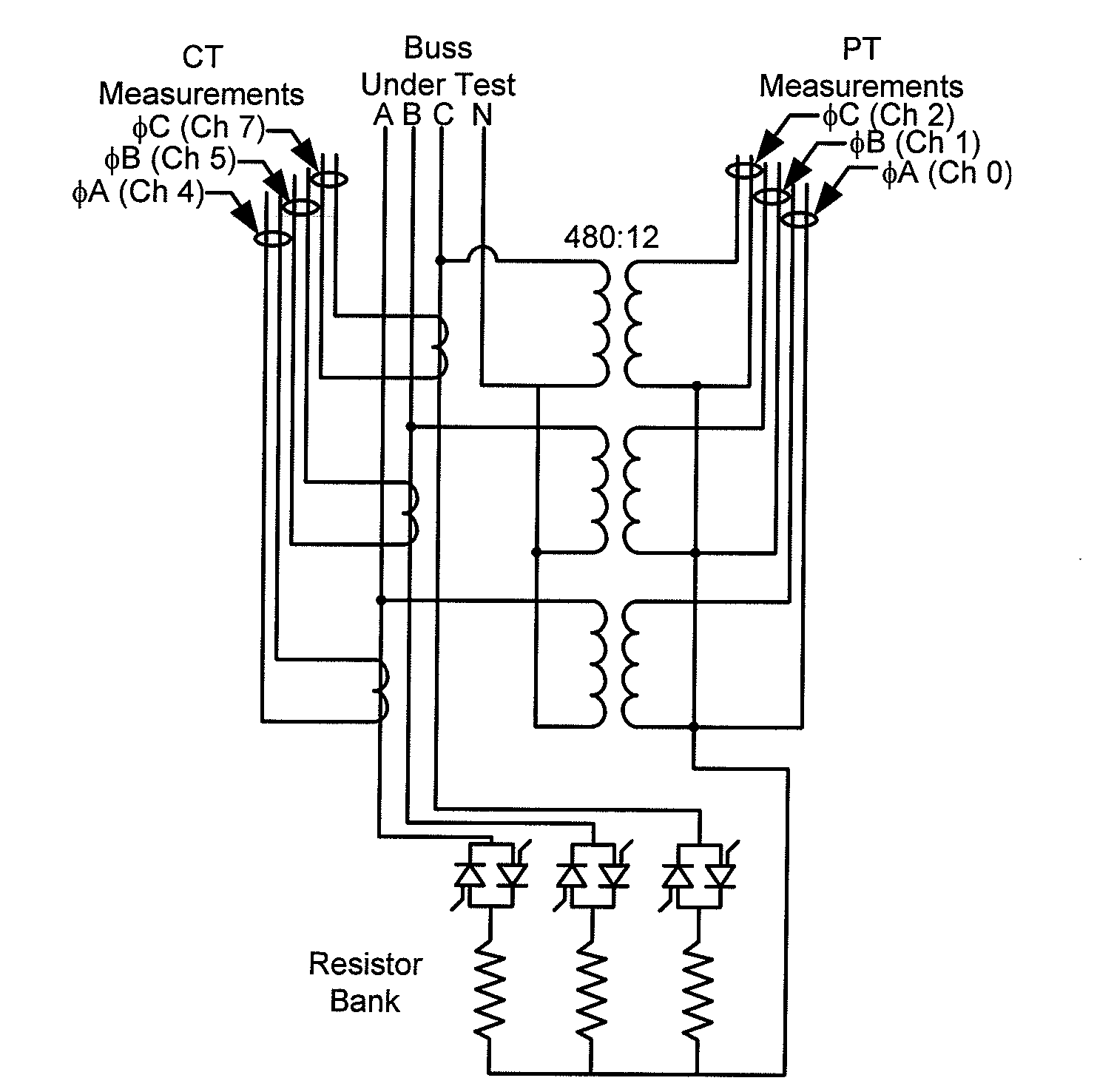
[0255]RIGGS HALL TEST SITE A: Upon completion of initial tests to determine viability of concept, the first IADD prototype was constructed in the PQIA lab. It is important to note here that this test was performed during the early stages of the IADD development, and the phase shift algorithms were less robust and non-linear transformers were used as the method of voltage detection.

[0256]The nameplate data on the transformer was given as 500 kVA, 12.47 kV-208 / 120Y V, with an impedance value of 5.66%. From industry tables for transformers of this type and size, the X / R ratio for this transformer is approximately 3.71. The cable from switchgear to the test panel in the PQIA laboratory was a 100 ft., four-wire run of 4 / 0 copper insulated conductor in aluminum conduit. From Table 9 of the NEC handbook, partially duplicated below, the impedance for this cable run was computed. The service impedance feeding the transformer was considered negligible because of the extremely high fault duty ...

example 2

Results

[0267]

Test #CurrentX / R Ratio 19593.182 29853.122 39733.106 49453.189 510472.901 69363.221 79473.131 89743.122 910183.0411010073.032119553.159129883.082139773.076149363.1371510043.050169843.0311710113.068189283.2081910183.026209573.136219633.1182210113.051239503.144249953.081259833.055Current StatisticsMean978.0046Standard Error6.1201Median976.6590Standard Deviation30.6006Sample Variance936.3965Kurtosis−0.5693Skewness0.2902Range118.3430Minimum928.3510Maximum1046.6940Confidence Level (95.0%)12.6313X / R StatisticsMean3.0988Standard Error0.0140Median3.1060Standard Deviation0.0702Sample Variance0.0049Kurtosis1.2636Skewness−0.5688Range0.3200Minimum2.9010Maximum3.2210Confidence Level (95.0%)0.0290

[0268]This test results in very stable, predictable results, with little variation from test to test. The test was also conducted at two different current levels and similar results were seen in both cases. Discrepancies in results have initially been attributed to unaccounted resistances in...


PUM


Abstract

Embodiments according to the present invention provide an Impedance-based Arc-Fault Determination Device (IADD) and method that, when attached to an electrical node on the power system and through observations on voltage, current and phase shift with a step load change, determine the effective Thevenin equivalent circuit or Norton equivalent circuit at the point of test. The device and method determine the expected bolted fault current at the test location of interest, which enables calculation of incident energy and the assignment of a flash-hazard risk category.

Description

CROSS REFERENCE TO RELATED PATENT APPLICATIONS[0001]This application is a continuation of U.S. application Ser. No. 11 / 838,831 filed Aug. 14, 2007, now U.S. Pat. No. 7,598,751 which claims benefit of the filing date of U.S. Provisional Application No. 60 / 837,537 filed Aug. 14, 2006, each of which are herein incorporated in their entirety by this reference.BACKGROUND[0002]Between five and 10 times a day, an arc flash explosion occurs in electric equipment in the United States that sends a burn victim to a special burn center, according to statistics compiled by CapSchell, Inc., a Chicago-based research and consulting firm that specializes in preventing workplace injuries and deaths.[0003]In response to these statistics and the obvious detrimental affects of arc fault incidents on workers, in the United States the Occupational Safety and Health Administration (OSHA) has begun enforcing recommendations by the National Electric Code (NEC) and National Fire Protection Association (NFPA) ...

Claims


Application Information

Patent Timeline
Patent Type & Authority Applications(United States)
IPC IPC(8): G01R27/28
CPCG01R19/2513G01R31/025G01R27/16G01R31/52
Inventor COLLINS, JR., EDWARD RANDOLPHSMITH, TIMOTHY LEEEMANUEL, RANDALL J.
Owner CLEMSON UNIV RES FOUND
Why Eureka
Try Eureka