Switching device

a technology of electrically conductive switches and switching devices, which is applied in the direction of relays, contacts, contact mechanisms, etc., can solve the problems of increasing the overall size of the switching device, increasing the cost, and serious damage to the switching device, and achieves low cost, easy production, manufacturing and operation reliably in a relatively small space.

Active Publication Date: 2010-02-04
TYCO ELECTRONICS LOGISTICS AG (CH)
View PDF22 Cites 36 Cited by
  • Summary
  • Abstract
  • Description
  • Claims
  • Application Information

AI Technical Summary

Benefits of technology

[0009]The invention provides a low cost high voltage switch assembly which can be easily produced. As all of the movements of the assembly are in a direction parallel to the axis of the armature, the assembly can be manufactured and operated reliably in a relatively small space. In addition, the linear movement on the angled contact provides for a positive electrical connection even in adverse environments.

Problems solved by technology

While these switching devices operate satisfactorily in normal applications, it has been found that under extremely high current conditions, e.g. short-circuit conditions, a repulsion force is generated which tends to part the pairs of contacts, which may cause serious damage to the switching device.
However, these devices, and in particular the pivoting arms, tend to be relatively complicated, which increases the cost and increases the overall size of the switching device.

Method used


Image

  • Switching device
  • Switching device
  • Switching device

Examples


Embodiment Construction

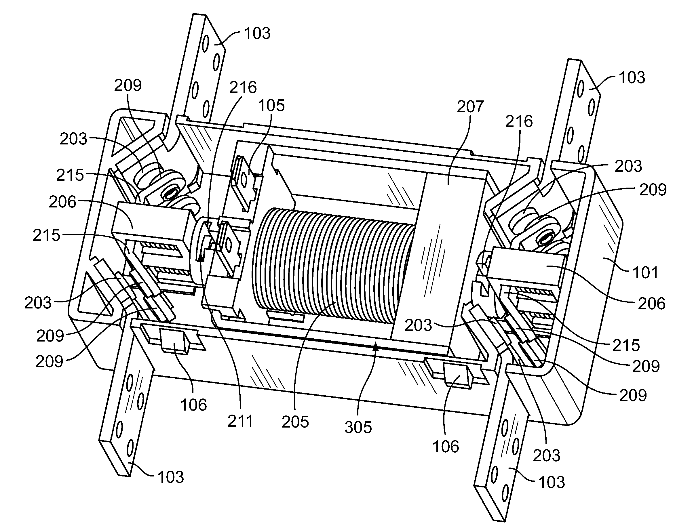
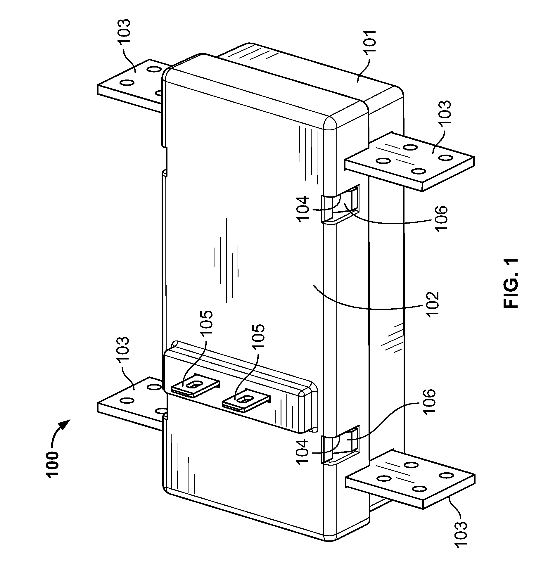
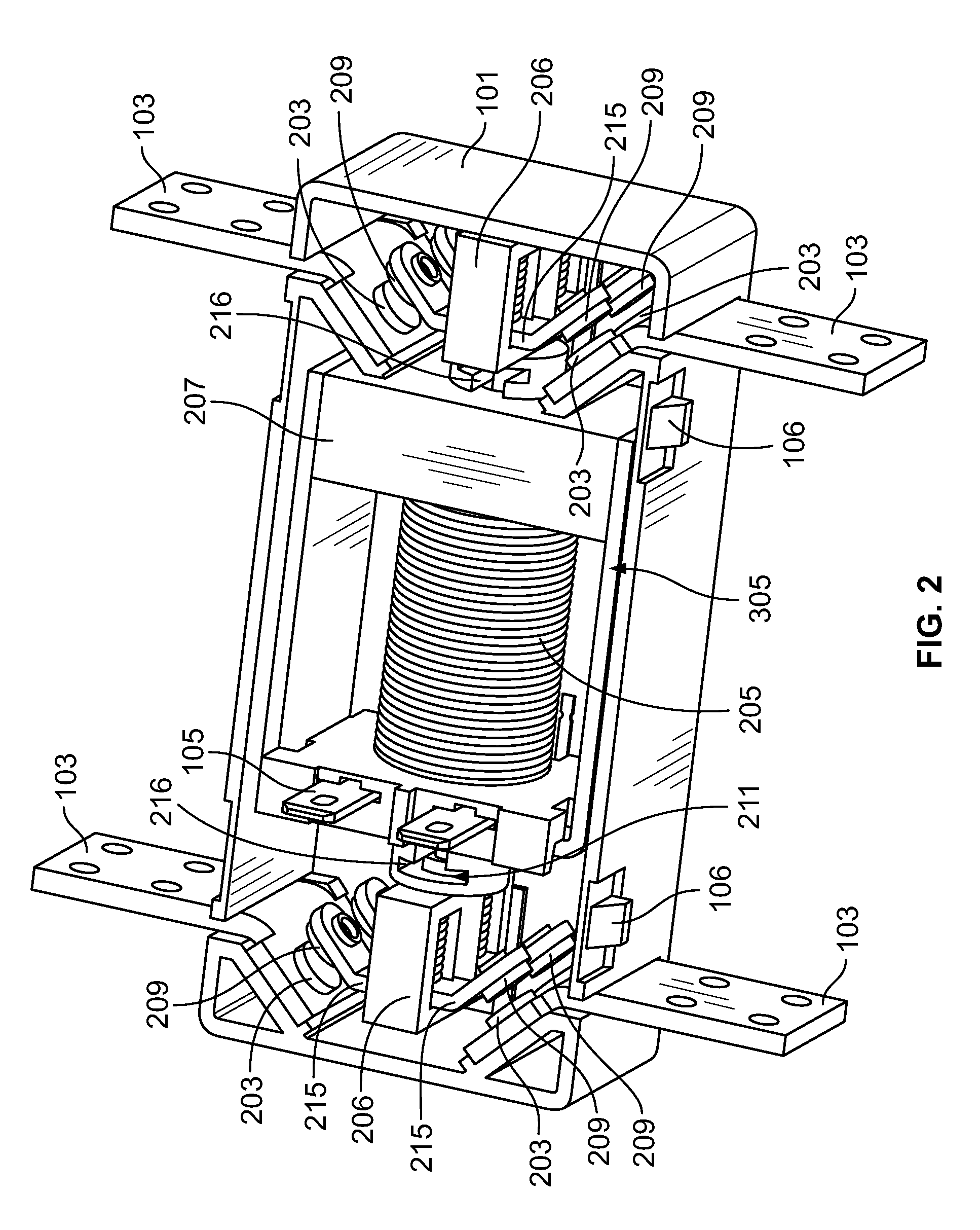
[0019]FIG. 1 shows a high current 200A switch or relay assembly 100 according to an embodiment of the present invention. While a high current switch is shown, aspects of this invention are equally applicable to all switches or relays. The switch assembly 100 includes a base housing 101 and a cover 102. Openings 104 in cover 102 receive latches 106 of base housing 101 therein to effectively latch the cover 102 to the base housing 101. The base housing 101 is configured with switch terminals 103 extending therethrough into the interior of base housing 101, providing electrical connectivity between switch terminals 103 and components within the base housing 101. Specifically, switch terminals 103 are in electrical communication with stationary contacts 203 (see, e.g. FIG. 2). In addition, coil terminals 105 extend through the cover 102 into the interior of the housing 101, providing electrical connectivity between coil terminals 105 and components within housing 101. Specifically, coil...


PUM


Abstract

The invention is directed to a switch assembly which can be used in situation in which the switch accommodates the flow of high voltage current. An actuator assembly with moveable contacts is moved by a motor driven armature. The moveable contacts are in electrical engagement with the stationary contacts when the armature is in the first position, and the moveable contacts are spaced from the stationary contacts when the armature is in the second position. By angling the stationary contacts and moveable contacts, the linear motion of the armature causes the moveable contacts to move across the surface of the stationary contacts as the armature approaches the first position. As all of the movements of the assembly are in a direction parallel to the axis of the armature, the assembly can be manufactured and operated reliably in a relatively small space. In addition, the linear movement on the angled contact provides for a positive electrical connection even in adverse environments.

Description

FIELD OF THE INVENTION[0001]The present invention is directed to electromagnetic switches and to contact systems related thereto and, in particular, to electromagnetic switches which can operate under high current conditions.BACKGROUND OF THE INVENTION[0002]Electromagnetic switches and relays known in the art typically consist of a multi-turn coil wound on an iron core forming an electromagnet. The coil electromagnet is energized by passing current through the multi-turn coil to magnetize the core. The magnetized coil attracts an armature to a first position, which is pivoted to connect or disconnect one or more sets of contacts. When no current is passed through the coil or the polarization of the current is reversed, the coil is moved to a second position in which the contacts are disconnected or connected respectively.[0003]While these switching devices operate satisfactorily in normal applications, it has been found that under extremely high current conditions, e.g. short-circui...

Claims


Application Information

Patent Timeline
Patent Type & Authority Applications(United States)
IPC IPC(8): H01H3/00
CPCH01H1/2025H01H1/2083H01H1/50H01H50/66H01H50/20H01H50/546H01H50/641H01H1/60
Inventor MOELLER, MATTHEW LENPARKER, DAVID GLENZARBOCK, KURT THOMAS
Owner TYCO ELECTRONICS LOGISTICS AG (CH)
Why Eureka
Try Eureka