Rectenna cover for a wireless power receptor

a wireless power receptor and rectenna cover technology, applied in the direction of antenna details, antenna adaptation in movable bodies, antennas, etc., can solve the problem of relative difficulty in maintaining rectenna configuration on moving structures, and achieve the effect of breaking the receive pattern

Active Publication Date: 2010-02-04
RAYTHEON CO
View PDF8 Cites 10 Cited by
  • Summary
  • Abstract
  • Description
  • Claims
  • Application Information

AI Technical Summary

Benefits of technology

[0004]According to one embodiment, a cover comprising a higher dielectric constant layer disposed outwardly from a lower dielectric constant layer is coupled to a rectenna operable to convert microwave power to electrical power. The cover receives microwave power, provides a substantial impedance match for a plurality of angles of incidence, and directs the microwave power to the rectenna. The impedance match is selected to broaden a receive pattern of the rectenna.
[0005]Certain embodiments of the invention may provide one or more technical advantages. A technical advantage of one embodiment may be that a rectenna cover may increase the efficiency of rectennas configured on moving structures, such as unmanned aerial vehicles. For example, a typical rectenna may be relatively non-directional and may require alignment with a transmitting station to receive power efficiently. Alignment, however, may be relatively difficult to maintain for rectennas configured on moving structures. In some embodiments, the rectenna cover may alleviate alignment requirements of known rectenna designs, thereby improving efficiency.

Problems solved by technology

Alignment, however, may be relatively difficult to maintain for rectennas configured on moving structures.

Method used


Image

  • Rectenna cover for a wireless power receptor
  • Rectenna cover for a wireless power receptor
  • Rectenna cover for a wireless power receptor

Examples


Embodiment Construction

[0012]Rectennas may wirelessly convert electromagnetic power to direct current (DC) power. In certain embodiments, a rectenna may receive microwave power in the microwave frequency range transmitted from a remote transmission station and convert the received microwave power to electrical power. Microwave transmitters may be relatively directional and may have a relatively narrow transmit pattern, which may degrade the power transfer efficiency of moving rectennas.

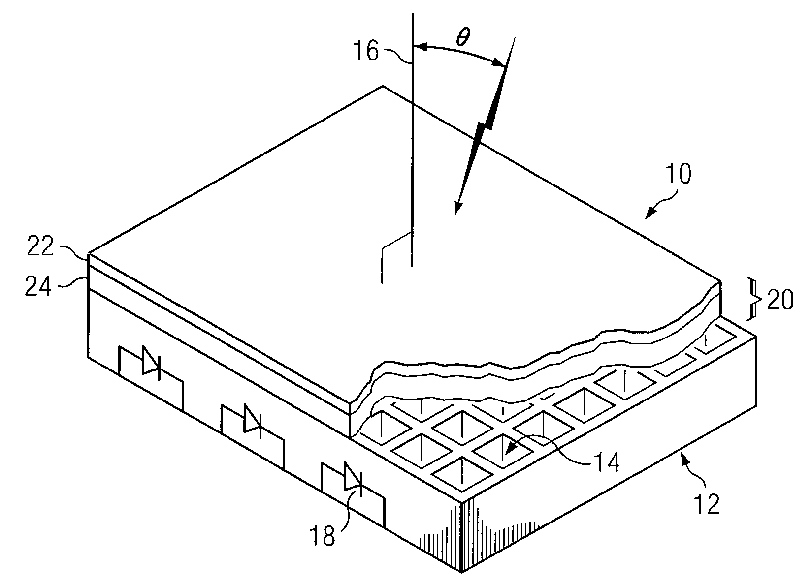
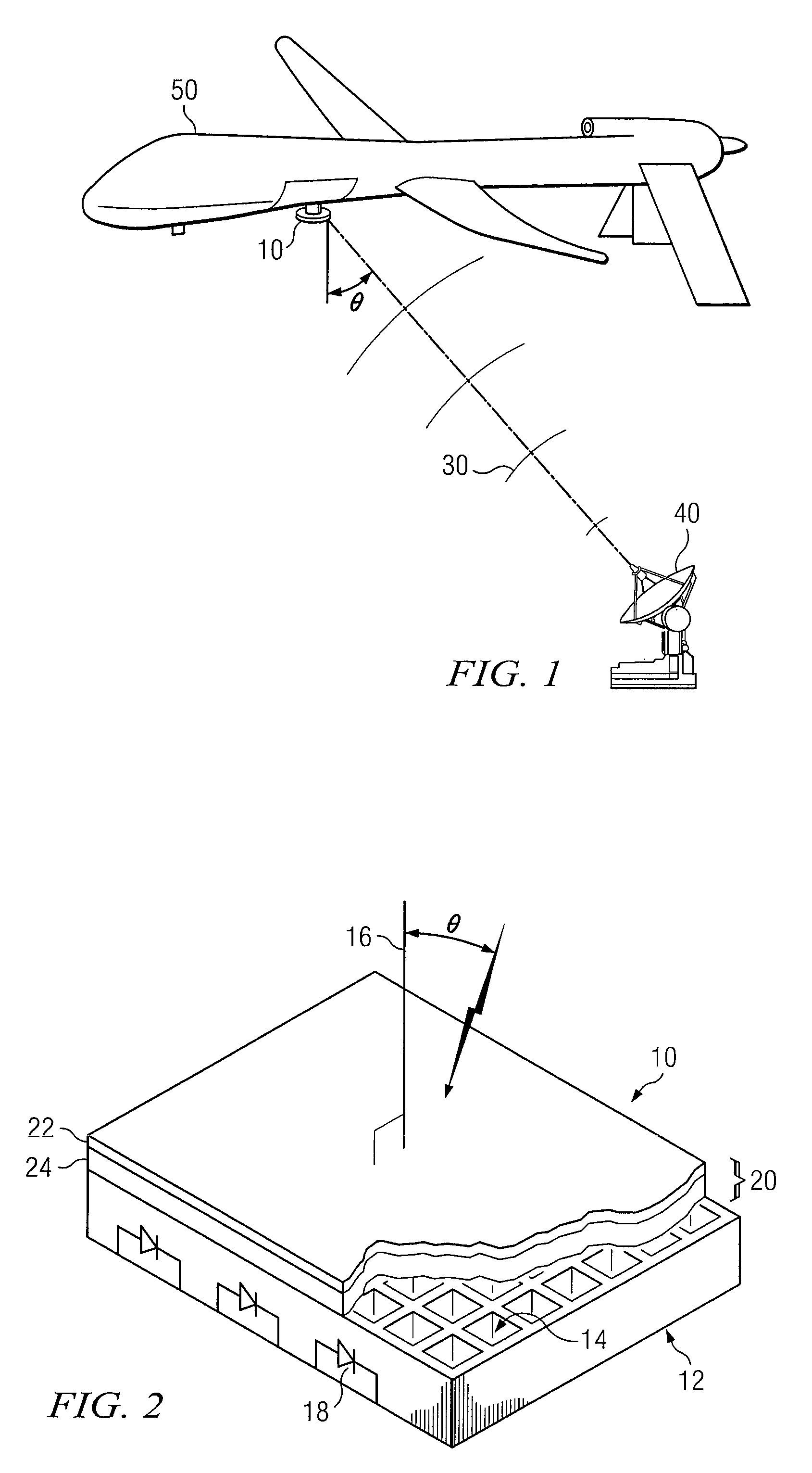
[0013]FIG. 1 shows one embodiment of a wireless power receptor 10 for wirelessly receiving microwave power 30 and converting the received microwave power 30 to electrical power. Microwave power 30 may comprise electromagnetic waves and may be transmitted to the wireless power receptor 10 from a remote transmission station 40. In some embodiments, wireless power receptor 10 may be configured on a moving platform. The moving platform may use power for movement. In certain embodiments, the moving platform may be a vehicle powe...


PUM


Abstract

According to one embodiment, a cover comprising a higher dielectric constant layer disposed outwardly from a lower dielectric constant layer is coupled to a rectenna operable to convert microwave power to electrical power. The cover receives microwave power, provides a substantial impedance match for a plurality of angles of incidence, and directs the microwave power to the rectenna. The impedance match is selected to broaden a receive pattern of the rectenna.

Description

RELATED APPLICATIONS[0001]This application claims priority to U.S. Provisional Patent Application Ser. No. 61 / 085,704, entitled “WIRELESS ENERGY RECEPTOR,” which was filed on Aug. 1, 2008. U.S. Provisional Patent Application Ser. No. 61 / 085,704 is hereby incorporated by reference.TECHNICAL FIELD OF THE DISCLOSURE[0002]This disclosure relates generally to wireless power receptors, and more particularly to a rectenna cover for a wireless power receptor.BACKGROUND OF THE DISCLOSURE[0003]A rectifying antenna (rectenna) is a type of antenna that generates electrical power by converting microwave power received wirelessly from a remote transmission station. Rectennas may have one or more electrically conductive elements designed to receive and rectify microwave power over one or more frequency ranges. Microwave power transmission may provide efficient power transfer due at least in part to its relatively narrow beamwidth and bandwidth.SUMMARY OF THE DISCLOSURE[0004]According to one embodi...

Claims


Application Information

Patent Timeline
Patent Type & Authority Applications(United States)
IPC IPC(8): H01Q1/42
CPCH01Q1/248H01Q1/422H01Q1/28
Inventor MCSPADDEN, JAMES
Owner RAYTHEON CO
Why Eureka
Try Eureka